11 Transmission Teardown
Hydro-Gear 0500 / 0650
11 - 10
1
12
2
14
17
9
6
7
8
13
18
16
10
11
3
5
15
4
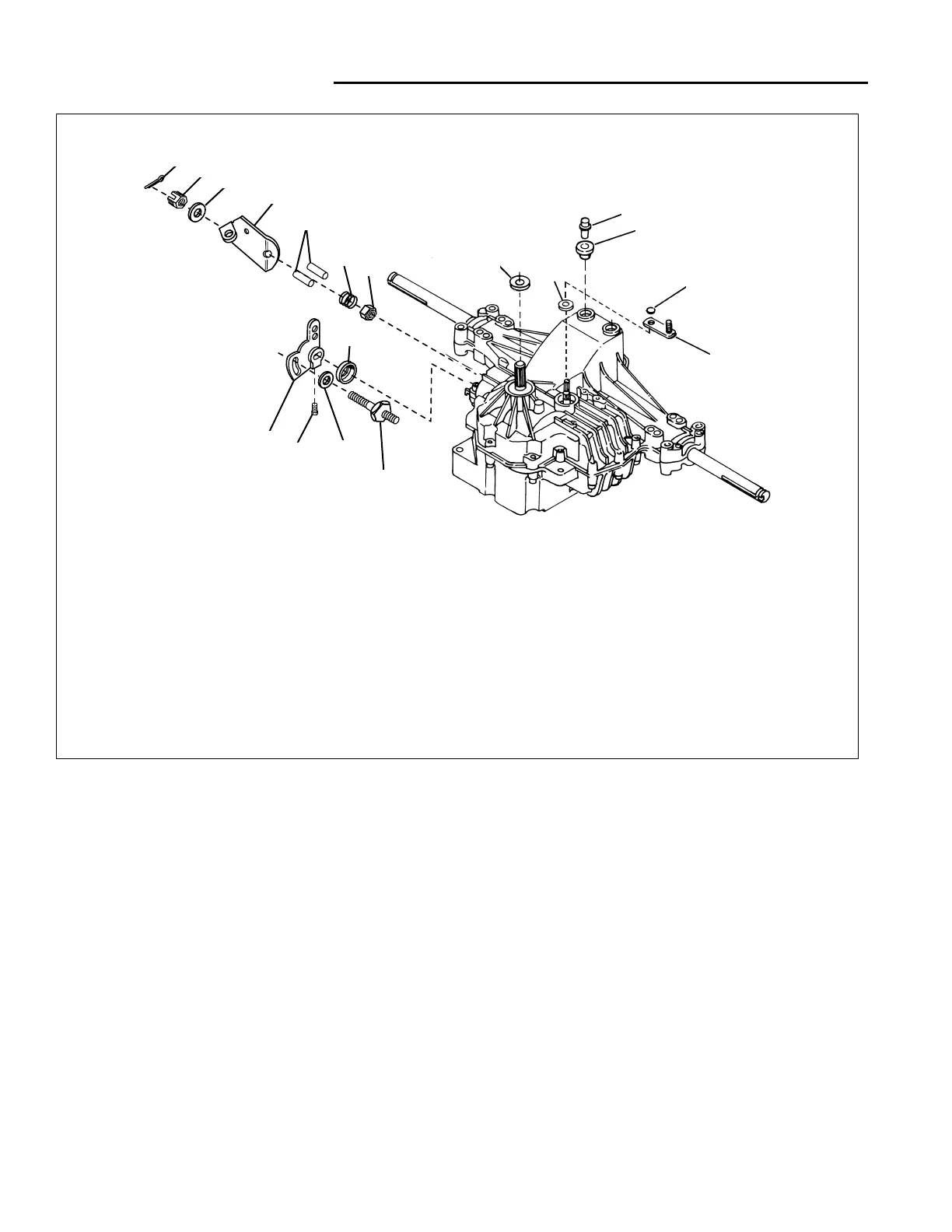
1 1 BREATHER ASSY.
2 1 BUSHING, Rubber
3 1 ARM, Bypass
4 1 SEAL
5 1 SET SCREW
6 2 ACTUATOR PIN
7 1 ARM, Brake
8 3 WASHER, 7/16 x 7/8 x 1/16
9 2 NUT, Hex, Lock, 5/16 x 24
10 1 SEAL, Lip
11 1 SEAL, Lip
12 1 RING, Retaining
13 1 CASTLE NUT, 5/16-24
14 2 PUCK, Dampener
15 1 ARM, Control
16 1 STUD, 5/16-24
17 1 SPRING, Helical Compression
18 1 COTTER PIN
Ref. Qty. Description Ref. Qty. Description
Figure 3. Brake and Transmission Control Linkages
Transmission Removal
See HYDRO-GEAR 0500 / 0650, TRANSMISSION
INSTALLATION & REMOVAL, Section 10.
Brake Assembly Service
The brake assembly components can only be serviced
by separating the transmission case halves. Follow the
DISASSEMBLY procedure and REASSEMBLY proce-
dure in this section. After the transmission is reassem-
bled perform the procedures listed under BRAKE AND
BRAKE SPRING ADJUSTMENTS, Section 4.
Remove External Components & Linkages
TRANSMISSION CONTROL ARM
1. Remove the set screw (Ref 5, Figure 3)
2. Remove the control arm (Ref 15) and dampener puck
(Ref 14).
BRAKE ARM
1. Remove the cotter pin (Ref 18, Figure 3) and castle
nut (Ref 13).
2. Remove the washer (Ref 8), brake arm (Ref 7), actu-
ator pins (Ref 6), compression spring (Ref 17), and
nut (Ref 9).
 Loading...