32 | Wiring the radar system
4.9 Radar processor 10 kw 25 kw: Connect interconnection cable
(AA010093/AA010094) to the radar processor
Note: Interconnection cables available AA010093 20 m (65.5 ft) AA010094 30 m (98.5 ft).
• Run the interconnection cable (AA010093/AA010094) from the scanner unit to the radar
processor.
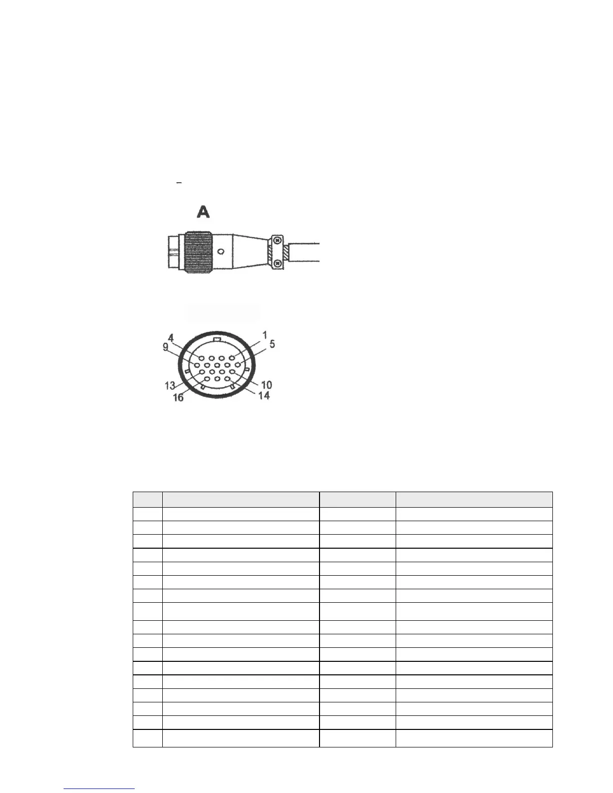
• Push the round connector (A) of the interconnection cable into the scanner connection on
the radar processor and tighten the locking nut.
• The front view of the interconnection cable is shown:
The interconnection cable pin details are provided here for information, in case the connector
needs to be removed to feed the cable, or in case the cable needs to be shortened.
Pin Color/Name AWG Size Signal name
1 Blue / Gray (thick) #16 Motor Ground
2 Purple / Brown (thick) #16 Motor Ground
3 White / Orange (thick) #16 Motor Power
4 Red / Green (thick) #16 Motor Power
5 Black / Sky (thick) #16 Scanner Ground
6 Black #22 Analog Ground
7 Drain wire (coax line) #24 Video Ground
8 No connection
Not used
9 Yellow / Pink (thick) #16 Scanner Power
10 Axis line (transparent insulation) #24 Video
11 Yellow (thin) #24 RS-485 Comm+
12 Green (thin) #24 Bearing Zero
13 White (thin) #24 RS-485 Comm-
14 Drain wire #24 Trigger Ground
15 Shield line #24 Trigger
16 Orange (medium) #22 Bearing Pulse
Shell Braid shield