Installation | 15
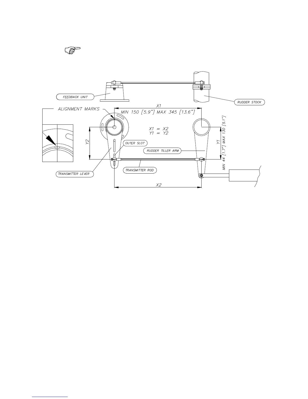
Carefully observe the alignment marks. A rudder
feedback alarm may be the result if the alignment
instructions as per Figure 2-5 are neglected.
Figure 2-5 Rudder feedback mounting (019356)
Note that the transmitter lever has two slots for the
transmitter link. The slots enable maximum flexibility to
provide the 1:1 mechanical linkage relationship. As a
starting point, set the transmitter rod to the inner limit of
the outer slot if possible. (Refer to Figure 2-5). Drill and
tap the rudder ti
ller arm so that the Y1 dimension is
equal to the Y2 dimension (Use 4.2 mm drill and 5 mm
tap). Attach the ball joint to the tiller arm, and connect
the transmitter rod to the ball joint at the rudder tiller
arm.
Tighten the mounting screws for both the feedback unit
and the transmitter rod ball joint.
Observe the feedback unit while someone turns the helm
wheel through the complete travel H.O. to H.O. and
verify that the mechanical linkage moves freely.