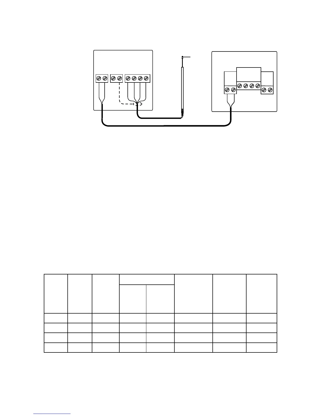
EasyManuals Logo
Home>Simrad>Autopilot System>AC12

Simrad AC12 User Manual

Simrad AC12
54 pages
To Next Page IconTo Next Page
To Previous Page IconTo Previous Page
Page #19 background imageLoading...
Page #19 background image
18 | Installation
Autopilot Computer
RUDDER
*
Non polarized
(color independent)
LFI3000 Mk2
Interface
LF3000
Linear
Feedback
*
TB2TB1
WHITE
BROWN
YELLOW
GREEN
BROWN
WHITE
Figure 2-9 LF3000/LFI3000 Mk2 connections
2.8 Drive unit installation
The relations between drive units, drive unit voltage,
autopilot computer, drive performance and interface to
the steering gear are shown in the tables below.
Refer to the connecting diagram for the different drive
units on page 19 onwards.
Instal
lation instruction for the drive units are found in the
manual for the individual units.
The maximum drive current capability of the AC12 and
AC42 autopilot computers are different. Use the table
below as reference and observe the notes on next page.
HYDRAULIC PUMPS
RAM CAPACITY
MODEL MOTOR
VOLTS
AUTO-
PILOT
COMPU-
TER
MIN
cm
3
(cu. in.)
MAX
cm
3
(cu. in.)
FLOW RATE
AT 10 bar
cm
3
/min
(cu. in/min)
MAX
PRESSURE
bar
PWR.
CONSUM-
PTION
RPU80 12V AC12 80 (4,9) 250 (15,2)
800 (49) 50 2,5-6 A
RPU160 12V AC42 160 (9,8) 550 (33,5)
1600 (98) 60 3-10 A
RPU300 12V AC42 290 (17,7)
960 (58,5)
3000 (183) 60 5-25 A
RPU300 24V AC42 290 (17,7)
960 (58,5)
3000 (183) 60 2,5-12 A

Questions and Answers:

Question and Answer IconNeed help?

Do you have a question about the Simrad AC12 and is the answer not in the manual?

Simrad AC12 Specifications

General IconGeneral
BrandSimrad
ModelAC12
CategoryAutopilot System
LanguageEnglish

Related product manuals