GPS Offset - sets an offset for calculating the GPS antenna position if you can’t •
physically locate the antenna exactly where you want it (e.g. over the centerline of
the boat).
Navigation - sets a variety of important functions and alarms
•
Rhumb line or Great Circle navigation
-
Range units: nautical miles, nautical miles and meters (when under 1000 meters),
-
nautical miles and feet (when under 1000 feet), statute miles, statute miles and
meters (when under 1000 meters), statute miles and feet (when under 1000 feet),
kilometers, or kilometers and meters (when under 1000 meters)
Cross-track error limit and alarm control
-
Waypoint pass criterion and distance: bisector line, perpendicular line, complex
-
(combination of bisector line and perpendicular line), distance to waypoint, or
manual
Waypoint Approach distance
-
Autopilot alarm control
-
Position - sets to either Lat/Lon or UTM, and some alarm limits. There is an
-
optional software package available to setup a user grid as well. The option is
explained in the Position, and CFG Position sections of this manual.
Time - sets appropriate offsets, and 12 or 24 hour clock mode.
-
Various NMEA input controls for sensors (i.e. speed log, wind instruments, etc).
-
You may have figured out by now that you will need to pay close attention to the
configuration screens. The good news is that you probably have to setup the CDU one
time and you can save the configuration data in a USB memory stick (or flash RAM) for
future use. The memory stick will allow you to easily restore or clone another MX51x to
your special configuration.
Dead Reckoning
The MX51x CDU is capable of Dead Reckoning (DR) calculation when appropriate
compass/heading and speed log sensors are connected and activated. Refer to the NAV4
and CFG sections of this document.
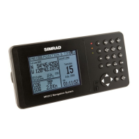
When the CDU is in the DR mode a DR icon is displayed in the upper right corner of the
screen.
NAV1 - The Panorama Screen
This screen is designed to give you a unique 3 dimensional look at the active route you
are to follow. It is typically referred to as a runway view because you can see navigation
markers, your course line, the cross-track error lines, and waypoint flags as you pass
them. Take a look at the example below.
If you don’t see the information described in this screen, you will need to create a route
in RTE1 screen first.
The somewhat triangular shape at the bottom center of the screen represents the bow
of the boat. Icons on the screen are always related to this object. The two dash lines
extending from the bottom of the screen towards the center of the screen represent your
cross-track error limits. The dotted line extending from the bow of the boat icon represents
your course line. The course line changes direction at the flags, which represent your
waypoints, and continues through to the end of the active route you entered in RTE1.
Notice that the cross-track error lines end at the first flag. As you pass the flag and start
the next leg of your course, these lines will be redrawn to reflect the course change. Icons
that you see left and right of your course are navigation markers that you define in the