EasyManua.ls Logo

Simrad MX500 User Manual

Simrad MX500
262 pages
To Next Page IconTo Next Page
Page #1 background imageLoading...
Page #1 background image
www.simrad-yachting.com A brand by Navico - Leader in Marine Electronics
Manual
Simrad MX500
Navigation System
English

Table of Contents

Question and Answer IconNeed help?

Do you have a question about the Simrad MX500 and is the answer not in the manual?

Simrad MX500 Specifications

General IconGeneral
Receiver Channels12
Update Rate1 Hz
DGPS ReadyYes
SBAS (WAAS/EGNOS) SupportYes
NMEA 0183 OutputYes
Display Resolution480 x 272 pixels
POIYes
Display Size5 inch

Summary

MX500 USB Feature Overview

USB Formatting

Instructions for formatting USB devices for the MX500.

2 Basic Operation

MX500 Configurations

Description of different MX500 system configurations.

Keypad & Display Description

Differential GPS Traffic Light Operation

GPS Traffic Light Operation

Mark Position/MAN OVER BOARD (MOB) Key

GOTO

Navigate

Dead Reckoning

NAV1 - The Panorama Screen

NAV2 - Basic Steering Information

NAV4 - Sensor Input Navigation

Route

RTE1 - The Active Route

Provides active route data for NAV and Plot screens.

RTE2 - The Route Bank

Creating a Multi-Waypoint Active Route

Insert By Number

Method to create a route by typing or scrolling waypoint numbers.

Choose in Bank

Method to create a route by selecting waypoints from the bank.

Insert New Waypoint

Method to define new waypoint coordinates and descriptions.

Insert Route

Method to copy a predefined route from RTE2 to active route.

Erasing an Existing Route

Maneuvering Within the Route

Inserting Waypoints or Routes into an Existing Route

PLOT1 - Relative to Boat

ETA Setup

SOG Based on Arrival Date & Time

ETA Based on Speed

Waypoint

Creating and Editing Waypoints

Make New WPT - Select Lat/Lon (W84), Lat/Lon Datum, or Range Bearing

Methods to create new waypoints using different coordinate systems.

Waypoint Lock/Unlock

Removing Waypoints

Downloading Waypoints & Routes to Other Devices

Downloading Waypoints to a Personal Computer

Uploading Waypoints from a USB Memory Stick

Mark or MOB

Man Over Board

Auxiliary

AUX1 - Alarm Log

Recording and managing system alarms.

Position

POS1 - Position Display (Large Digits)

Largest presentation of coordinate information.

POS2 - Position, Altitude, Magnetic Variation, & Time

POS3 - Position & Log

GPS

GPS1 - GPS Status Screen

Information on available satellites and their signal strength.

GPS2 - GPS Health Screen

GPS5 - RAIM Status Screen (for RAIM Enabled Models Only)

GPS6 - DGPS STATUS

3 Advanced Operation

Configuration

Setup and control of the receiver's primary functions.

Alarms

Quick view of active and inactive alarms.

Anchor - Anchor Watch Alarm

COG SOG - Course & Speed Filter Settings & Setup

Compass - External Compass Input & Magnetic Variation Table

Datum - Current Position Calculation

Depth - NMEA Input Control

DGPS - DGPS Configuration

DR - Dead Reckoning

Dual Control - Dual Station Control

GPS - Elevation Mask Control

Init Pos - Initial Position Entry

Feature to help the GPS receiver get a faster first position fix.

LAN - Local Area Network

LAN Output (NMEA 0183 OVER IP)

Log - Speed Log Input (Pulse or NMEA 0183)

Memory

Navigation - Navigation Method & Waypoint Pass Criterion Control

Navigation

Setting navigation mode to Rhumb Line or Great Circle.

XTE Limit

XTE Alarm

Enabling an alarm for exceeding the XTE Limit.

WPT Pass Criterion

Defining methods for determining waypoint passage.

Autopilot Alarm

NMEA Out 1 and 2 - NMEA 0183 Output Data Control

MX500 NMEA Out Menu

Operation - General Setup and Control Settings

Organizer - Automated Message Reminders

Position - Positioning Reference, Mode, & Alarm Control

Reference System

Selecting the coordinate system for position display.

Alarm For High HDOP

Setting an alarm for high HDOP values indicating poor accuracy.

HDOP Alarm Limit

Defining the HDOP value that triggers an alarm.

Alarm If No Update

Alarm for loss of position fix calculation.

Printout 2 - Printer Output Control

Security

Time - Mode and Format Control

USB - USB Mass Storage Configuration

Wind

Wpt & Rte Input - Uploading Waypoints into the Receiver

4 Installation

List of Components

Standard parts included with the MX500 model.

MX500 Electrical Installation Drawings

Figure 4.8 MX500 Basic Wiring Diagram

Detailed wiring diagram for the MX500.

Figure 4.9 Power/Data Cable Diagram

Pinout and wiring for the power/data cable.

Figure 4.10 Auxiliary Cable Diagram

Pinout and wiring for the auxiliary cable.

Figure 4.12 MX500 Dual Control Configuration

Diagram illustrating dual control system setup.

Figure 4.13 MX500 Dual Control Integrity Monitoring Configuration

Diagram for dual control integrity monitoring setup.

Figure 4.14 MX500 Multiple Unit Control Configuration

Diagram for multiple unit control system configuration.

Installation notes

Wire Preparation Procedure

External Power

Power supply requirements and polarity protection.

MX GPS Antenna Installation

Antenna Location

Recommendations for optimal antenna placement.

MX Smart Antenna Configurations

External Differential Connection

MX500 Navigator Installation

Turning Power On and Off

Equipment Interfacing

Speed Over Ground Pulse Output

External Alarm Output

NMEA Interface

MX500 NMEA 0183 Sentences

Input NMEA 0183 Sentences

Dual Control (Remote) Interface

MX500/BRIM Dual-Control with Integrity Monitoring Feature

Dual-Control Integrity Monitoring

Comparing GPS solutions between two MX500 units.

Multiple Unit Control Configuration

Troubleshooting Guide

Memory Backup Battery

MX500 PC Interface

Software Update Procedure

Memory Clear Procedure

USB Device Formatting Procedure

5 Specifications

MX521/MX525 Smart D/GPS Antenna

Technical specifications for the smart D/GPS antennas.

MX500 Control and Display Unit (CDU)

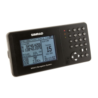
Specifications for the MX500 CDU display and keyboard.

Power

MX500 CDU

Power consumption and supply voltage specifications.

MX500 CDU Inputs and Outputs

Appendix B - Beacon List

Appendix C - Engineering Mode

CDU Cold Start - Clearing Memory to Factory Default

GPS3 - Visible Satellite Information

GPS4 - GPS Position Uncertainty

MX Ant. Reset & CSI Reset Tools

MX Ant Reset Procedure

Steps to reset the GPS engine or CSI reset.

Appendix D - Multiple Unit Control (Via LAN Connection)

Dual Control Configuration

Connecting one MX500 as Master and another as Slave.

Dual-Control Integrity Monitoring

REQUEST FOR SERVICE

Related product manuals