Auxiliary (8-pin) Cable:
This is a 4-pair twisted cable. Below are the color and
signal designation of the wires:
Pin 1 --- Yellow ------- Ext. MOB Input
Pin 2 --- Green -------- GND.
Pin 3 --- Blue ----------- Dry Contact 1
Pin 4 --- Purple -------- Dry contact 2
Pin 5 --- Grey ----------- Speed Log IN +
Pin 6 --- White --------- Speed Log IN -
Pin 7 --- Orange ------- Speed Log Out +
Pin 8 --- Brown --------- Speed Log Out -
An optional Junction Box with all wires installed is avail-
able for easy plug & play installation.
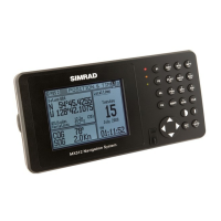
External Power
The MX500 will to operate on 12 ~ 32 VDC supply. It can
tolerate voltages no lower than 10 volts and no higher
than 35 volts. It draws about 1 Ampere at 12 VDC (with
an antenna connected). Power wire colors are red (+) and
black (-). Even though the navigator has a reverse polar-
ity protection device, we recommend that the installer
observe proper polarity before hooking up the power
leads. It is recommended using a 2 amp. fuse in line with
the red wire as close to the battery as possible. This not
only protects the navigator but also the cabling.
Navigator Grounding
The internal electronic circuits of the navigator are
isolated from the external power supply. Connect the
ground stud to ship’s seawater ground to avoid static
charge build up.
‘Seawater ground’ is any electrically conductive material
that is directly in contact with sea water.