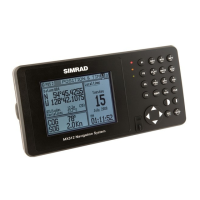
MX Smart Antenna Configurations
10-Pin Conn. (MX521/MX525) 10-Pin Conn. (MX421-10)
Pin
#
Wire
Color
MX521
DGPS
MX525
DGPS
MX421-10
GPS
MX421-10B
DGPS
1
BLK/
SHIELD
Negative Ground
2 RED
+10.5 ~ 32 VDC
3 BLU
Proprietary Message (LPM) In (-)
4 BRN
Proprietary Message (LPM) In (+)
5 ORG
GPS Out (-)
6 GRN
GPS Out (+)
7 YEL
Beacon Status
Out (-)
RTCM In (-)
Beacon Status
Out (-)
8 WHT
Beacon Status
Out (+)
RTCM In (+)
Beacon Status
Out (+)
9 PRPL
1 PPS (+)
10
PRPL/
GRY
1 PPS (-)
Beacon Status
Out (-)
Beacon Status
Out (+)
RTCM In (+)
RTCM In (-)
RTCM In (+)
RTCM In (-)
For MX575A connection, please refer to page 167 of this
manual.
Antenna Cable Options
The pre-wired antenna cable assembly is not provided
with the MX antennas. The dealer/installer has to de-
termine the length needed and specify the length when
ordering the cable. The following cable lengths are avail-
able:
3 meter, twisted pair, 10-lead cable -- P/N 3508 102 •
70150
20 meter, twisted pair, 10-lead cable -- P/N 3508 102 •
70170
40 meter, twisted pair, 10-lead cable -- P/N 3508 102 •
70180
60 meter, twisted pair, 10-lead cable -- P/N 3508 102 •
70640
80 meter, twisted pair, 10-lead cable -- P/N 3508 102 •
70185