Antenna Installation
Antenna Location
The MX series smart antennas (MX421, MX521, MX575 & MGL3) are designed for exposed
installation. They should be mounted with a relative clear view of the horizon as shown in page 120 of
this manual. Do not, mount the antenna on top of a very tall mast, as this may degrade the COG and
SOG calculations, particularly when in DGPS mode. Ensure the antenna is placed outside the beam
path of transmitting radar (typically +15° horizontally from the array’s center point) and INMARSAT
satcom (A, B, C, or M; typically +10° from the array’s center point in any of the possible transmitting
directions and at least 5 meters from any side lobe or back lobe direction). The GPS antenna should
be mounted below and at least 5 meters away from these types of antennas. Do not place it within 3
meters of a SSB or VHF radios or their antennas.
Antenna Options
Four antenna models can be used with the MX51x, namely:
•
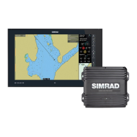
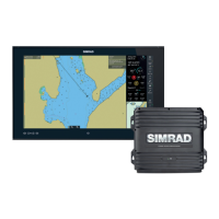
MX421 D/GPS smart antenna
• MX521A D/GPS smart antenna
• MX525A D/GPS Sensor
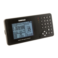
• MX575A Satellite Compass
Wiring hookup to the MX421, MX521A, and MX525A antenna models are the same. The
12 VDC drive voltage to the antenna is normally provided by the MX51x CDU.
Antenna Connector
The 10-pin connector at the bottom of the antenna housing provides the necessary
interfacing between the smart antenna and the MX51x CDU. Refer to the MX antenna
wiring diagram shown in the Installation section of this manual.
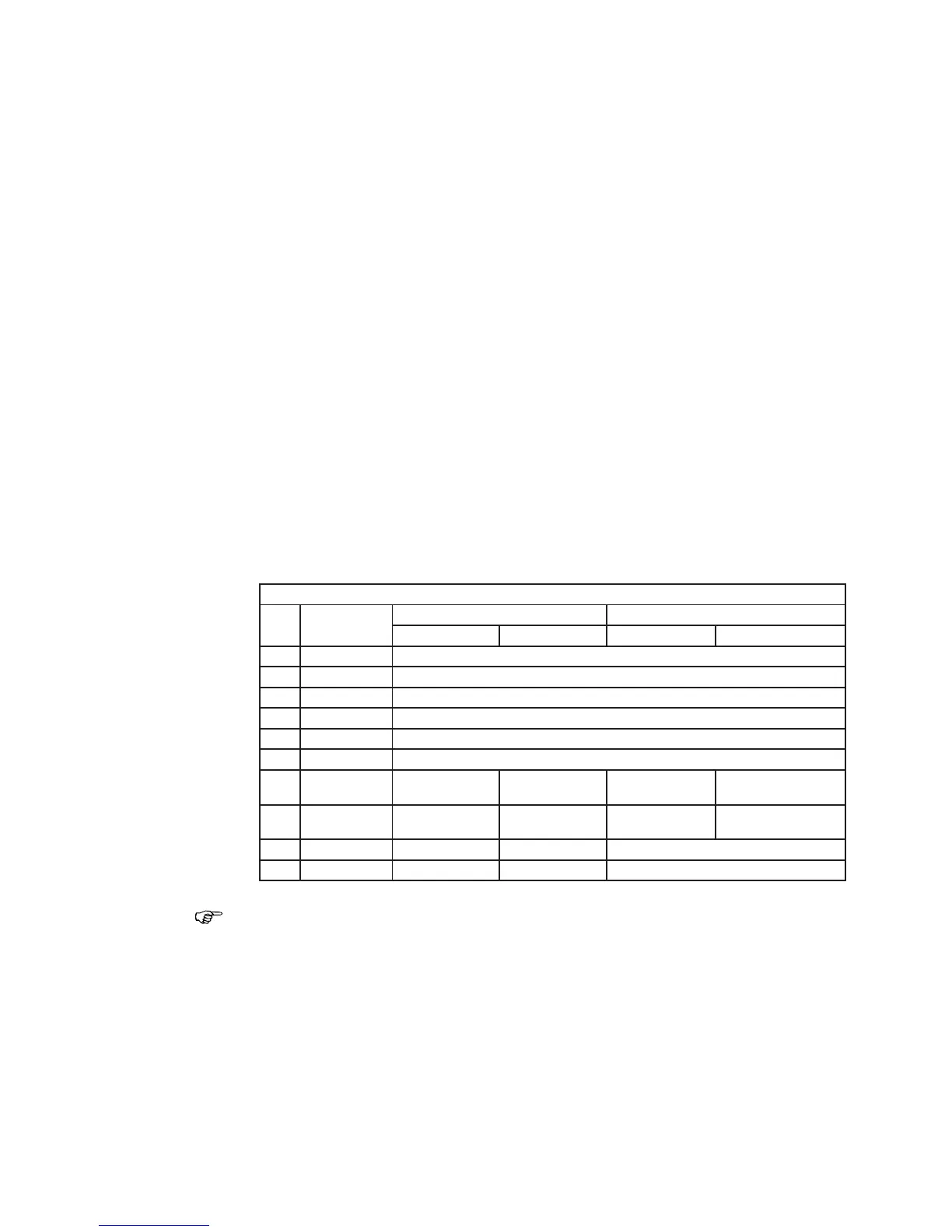
MX Smart Antenna Congurations
Pin
#
Wire Color
10-Pin Conn (MX521/MX525) 10-Pin Conn (MX421-10)
MX521 DGPS MX525 DGPS MX421-10 GPS MX421-10B DGPS
1 BLK/SHIELD Negative Ground
2 RED +10.5 ~ 32 VDC
3 BLU Proprietary Message (LPM) In (-)
4 BRN Proprietary Message (LPM) In (+)
5 ORG GPS Out (-)
6 GRN GPS Out (+)
7 YEL
Beacon Status
Out (-)
Beacon Status
Out (-)
RTCM In (-)
Beacon Status
Out (-)
8 WHT
Beacon Status
Out (+)
Beacon Status
Out (+)
RTCM In (+)
Beacon Status
Out (+)
9 PRPL RTCM In (+) RTCM In (+) 1 PPS (+)
10 PRPL/GRY RTCM In (-) RTCM In (-) 1 PPS (-)
For MX575 connection, please refer to page 127 and page 140 of this manual or to the
MX575 Installation & Operation Manual.
Antenna Cable Options
The MX smart antenna does not come standard with an antenna cable assembly. The
dealer/installer has to determine the length required and order the appropriate cable
length. The following cable sizes are available:
•
3 m, Antenna Cable (with 2 connectors) -- P/N 500-100-1008
•20 m, Antenna Cable (with 2 connectors) -- P/N 500-100-1006
•40 m, Antenna Cable (with 2 connectors) -- P/N 500-100-1007
•60 m, Antenna Cable (with 1 connector) -- P/N 3508-102-70640
•60 m, Antenna Cable (with 2 connectors) -- P/N 500-100-1009
•80 m, Antenna Cable (with 1 connector) -- P/N 3508-102-70185