Instruction manual
20220562E 23
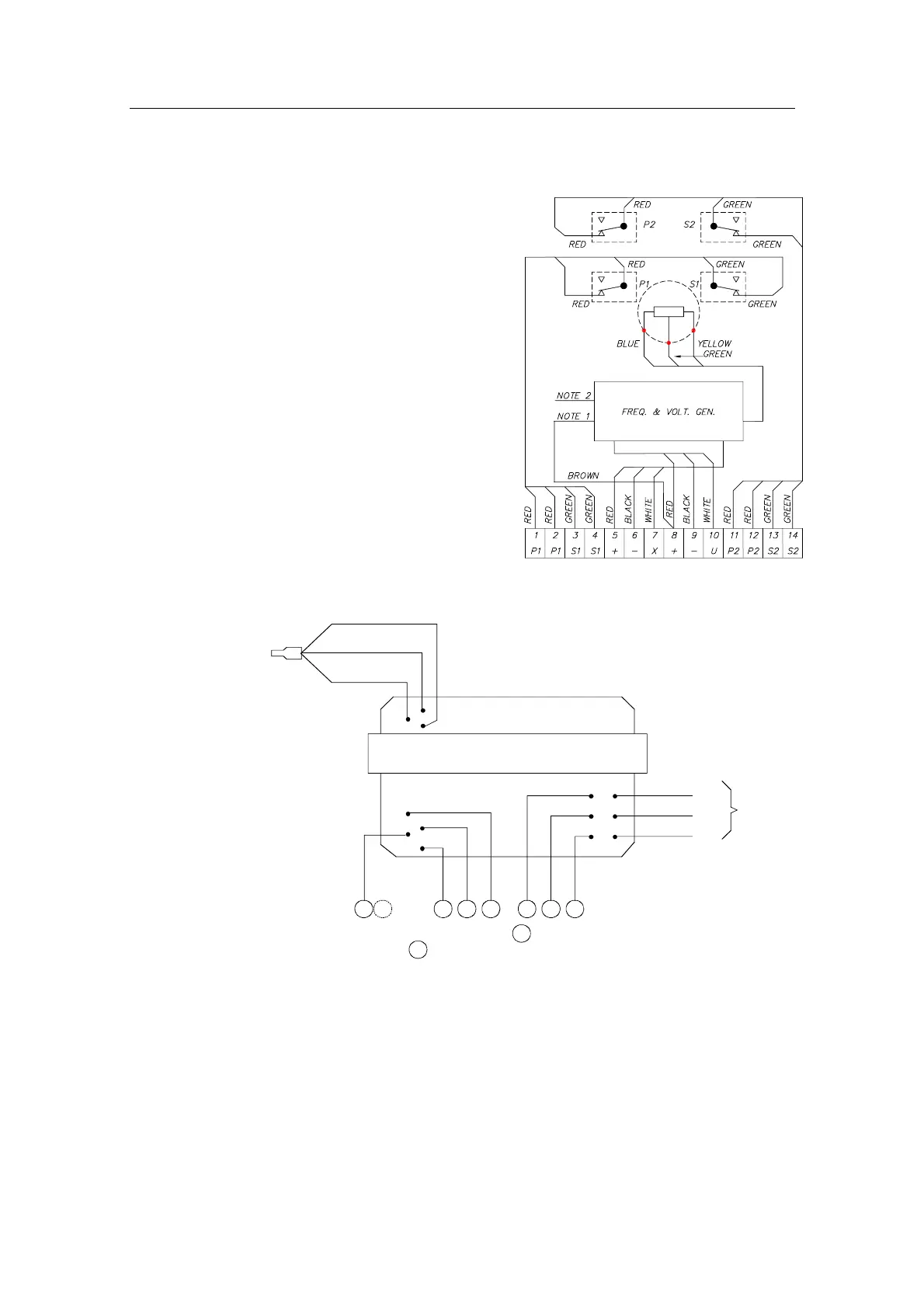
2.5 Other rudder angles
The RF14XU is normally
delivered for ±45 degrees
rudder angle (violet, brown
and pink leads are not
connected). For ±60 degrees,
connect brown lead to
terminal 10. For ±70 degrees,
connect pink to terminal 10
and for ±90 degrees, connect
the violet lead to terminal 10.
White lead must remain
connected. To reverse the
indicator deflection, the brown
lead to terminal 8 must be
connected to terminal 9. All is
referred to connections
between the terminal board
and the internal of RF14XU,
see Fig. 2-12
VIOLET
BROWN
PINK
BLACK
RED
WHITE
WHITE
BLACK
RED
BLUE (GND)
YELLOW (+5V)
GREEN (WIPER)
NOTE 1
NOTE 2
9810 765
RF14XU ELECTRONIC MODULE
(VIEWED FROM BACK SIDE)
NOTE 1: Brown lead normally connected to .
Move to to invert the rudder indicator deflection.
NOTE 2: Normally connected for +/-45° rudder angle (violet, brown and pink leads are
not connected). For +/-60° connect brown lead to terminal 10, for +/-70° connect
pink lead to terminal 10, for +/-90° connect violet lead to terminal 10.
White lead must remain connected.
BROWN
89
8
9
TO
POT.
METER
Fig. 2-12. RF14XU, Internal wiring
Note ! Inside the Feedback Unit cover, a piece of moisture protecting sponge
is attached. The sponge produces a corrosion preventive gas, and to
increase the long-range efficiency of the gas, avoid keeping the unit
open over long time periods.