Simrad RI9 Rudder Angle Indicator
6 20220562E
Connection to autopilot junction units
All interconnection cables should be screened, 1.5 mm
2
(AWG14)
wires. See Fig. 1-4 to Fig. 1-9 for connections to the different
autopilot junction units.
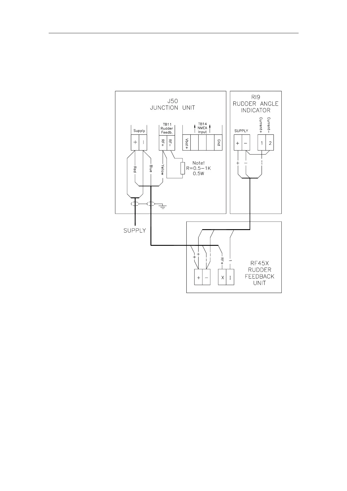
Fig. 1-4 RI9 in an AP50 system with RF45X
The above connection diagram shows how to connect an RI9 Rudder
Angle Indicator to an AP50 system with RF45X Rudder Feedback
Unit.
This connection gives full functioning indicator(s) also with the
autopilot switched off. To have the indicator(s) switched off with the
autopilot, connect indicator(s) and rudder feedback supply+ to J50
Vbat+ instead of J50 Supply+.
Note ! The resistor R (0.5-1K, 0.5W) has to be mounted. The resistor is not
supplied by Simrad.