Instruction Manual
20220562E 9
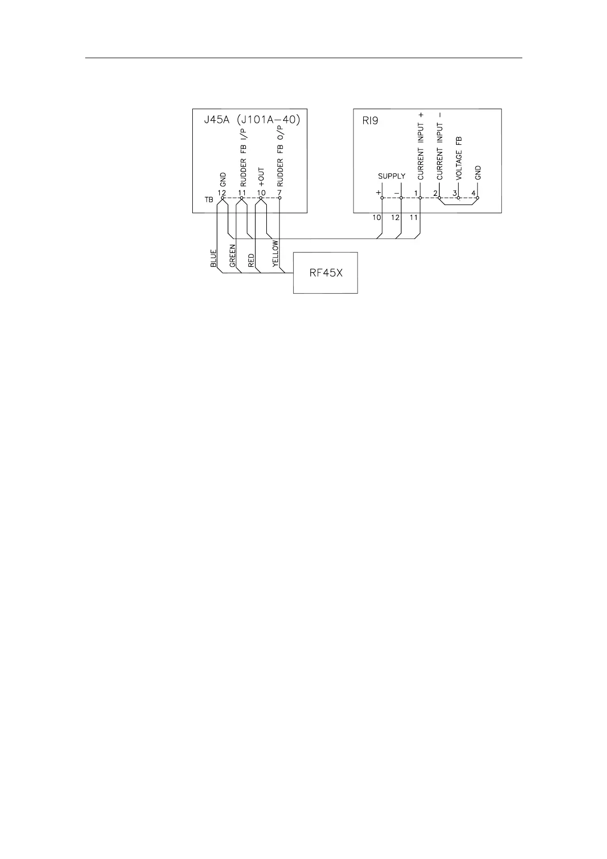
Fig. 1-9 RI9-J45A Wiring diagram
RI9 set-up
The RI9 indicator is calibrated for voltage input signal (RF14XU
Rudder Feedback Unit). Assuming that the mechanical linkage is in
accordance with the instruction on Fig. 2-2 adjustment of the
trimpotmeters marked Voltage FB, G (=Gain) and O (= Offset) is not
necessary.
If the RI9 is indicating wrong/opposite direction, the meter deflection
can be reversed by moving “jumper” ST1 from “Norm” to “Inv”.
Note ! The “Norm”/“Inv” jumper does not affect the meter deflection for
current input signal. If the meter deflection has to be reversed, it must
be made in the feedback unit as described for RF45 and RF14XI.
If the current input signal is used (RF100, RF140, RF14XI, RF45), the
reference inside RI9 has to be changed. This is done by opening the
RI9 and move the “jumper” ST3 from “U” to “I” position (see
Fig.
1-10).