Instruction manual
20220562E 15
2.3 Installation
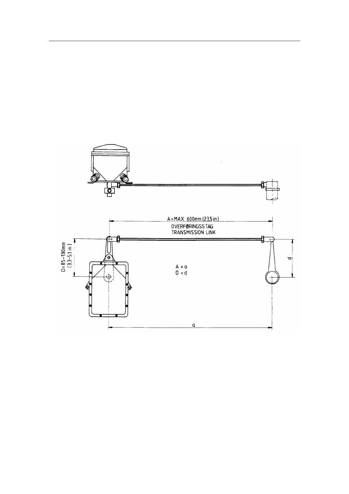
Before installation check that the alignment mark on the mounting
plate agrees with the mark on the shaft. Bring the rudder to midships
position. The feedback unit should be mounted on a plane surface and
secured by bolts through the three holes in the mounting plate. It
should be linked to the rudder in accordance with Fig. 2-2. It is
important that the linkage is linear, i.e. the A-a and D-d are pairs of
equal length. This will give a 1:1 ratio between the rudder travel and
that of the feedback unit shaft.
Fig. 2-2. RF14XU - Mounting
2.4 Wiring
Wiring to the RI9 is shown in Fig. 2-4 and Fig. 2-5. Fig. 2-6 - Fig. 2-8
show the combination of RI9 and Panorama connected to the
RF14XU.
Fig. 2-9 - Fig. 2-11 show the combination of RI9 and
Panorama Mk2 connected to the RF14XU The cables are carried
through cable glands and connected to the terminal board. To avoid
any mechanical damage, the cables should be run in a conduit between
the rudder feedback unit and the rudder indicator(s). The cable screen
must be connected to the internal ground terminal. Ref. picture below.