Simrad RI9 Rudder Angle Indicator
24 20220562E
2.6 Adjustments
After having tightened all mechanical parts and connected all cables,
the following adjustment must be carried out:
1. Check that the rudder is set to midship position.
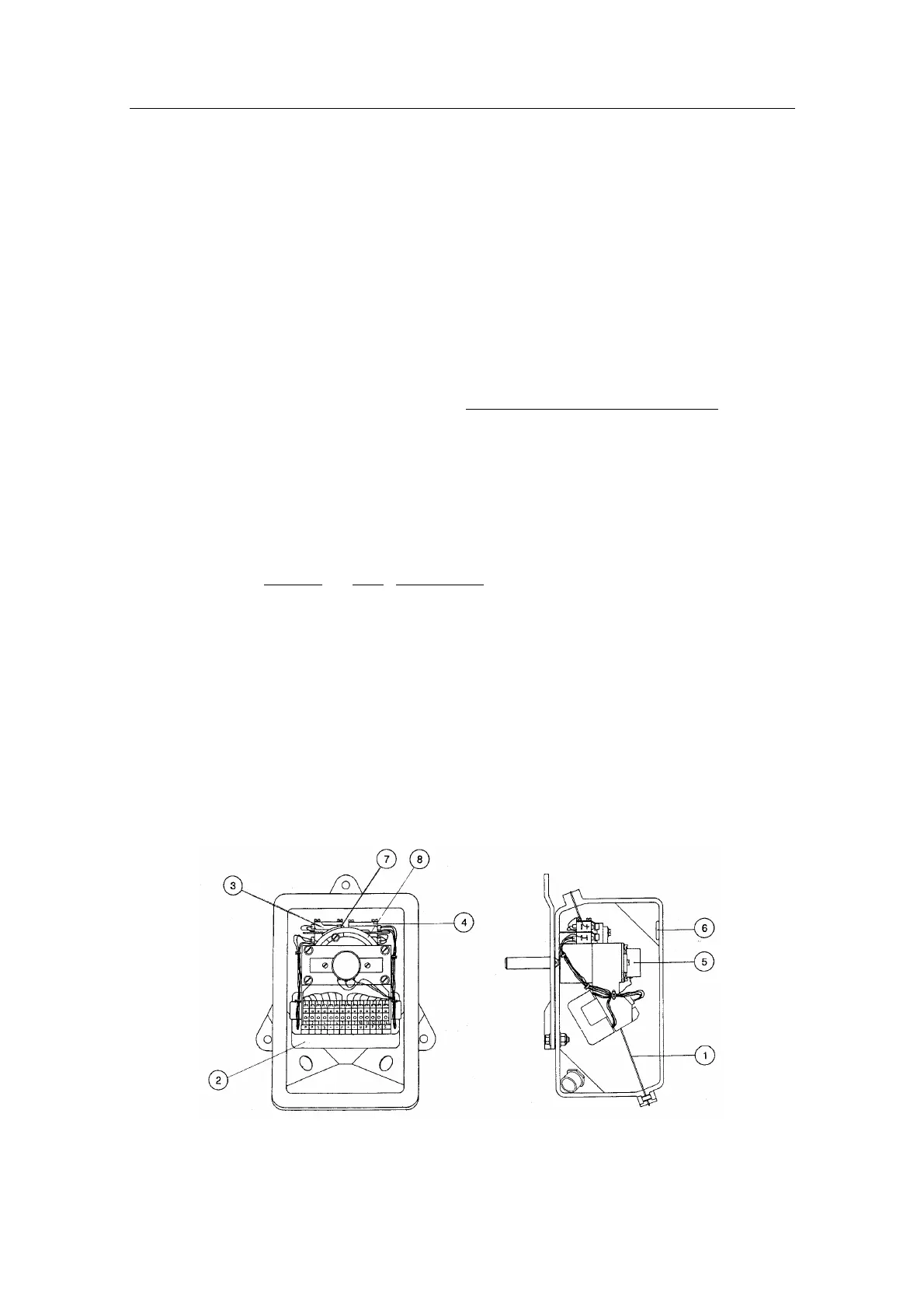
2. Measure the voltage between "U" and "+", respectively "-" on the
RF14XU terminal board. If the two measured voltages do not have
the same numerical value, loosen the two clamping screws on the
potentiometer and turn the potentiometer housing. (Fig. 2-13 pos.
5) until the same numerical value is measured. The RF14XU is
now set to midposition. Tighten the two clamping screws.
After installation, the cable glands should be sealed with silicon to
prevent water from seeping in. Also apply silicon grease to the gasket
between the bottom and top cover.
2.7 Spare parts
Part no. Pos. Description
22504005 Transmission Link
44132306 Ball joint
22500300 Shaft coupling
22500458 1 Gasket
22501605 2 Electronic XU drive module
44105120 3 Actuator
44105146 4 Limit switch
44118388 5 Potentiometer 5Kohm
44132033 6 Corrosion inhibitor sponge
22500284 7 Activator block
22500276 8 Activator disc
Fig. 2-13 RF14XU - Spare Parts