Instruction Manual
20220562E 7
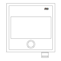
Fig. 1-5 RI9 in a AP50 system with RF14XU
The above connection diagram shows how to connect an RI9 Rudder
Angle Indicator to an AP50 system with RF14XU Rudder Feedback
Unit.
Notes ! This configuration is for 24VDC only.
The resistor R (0.5-1K, 0.5W) has to be mounted. The resistor is not
supplied by Simrad.
The RI9 Rudder Angle Indicator is connected to the U-terminal on
RF14XU.
The connection shown above gives full functioning indicator(s) also
with the autopilot switched off. To have the indicator(s) switched off
with the autopilot, connect indicator(s) and rudder feedback supply+
to J50 Vbat+ instead of J50 Supply+.