39
Simrad RS10 Operation and Installation Manual
7-9 Wiring Details
In case a cable is cut accidentally the pinouts are shown here for information only.
Do not cut cables intentionally.
Cable Pinout Color
1 VHF Antenna
2 Power 1. 13.6V DC + Red (thick cable)
2. 13.6V DC - Black (thick cable)
3 External speaker 1. EXTERNAL SPK + White (thin cable)
2. EXTERNAL SPK - Black (thin cable)
4 GPS connector (pins used) 4. NMEA IN + Yellow
5. NMEA IN - Green
2.
Not used
Not used
6. Not used
Not used
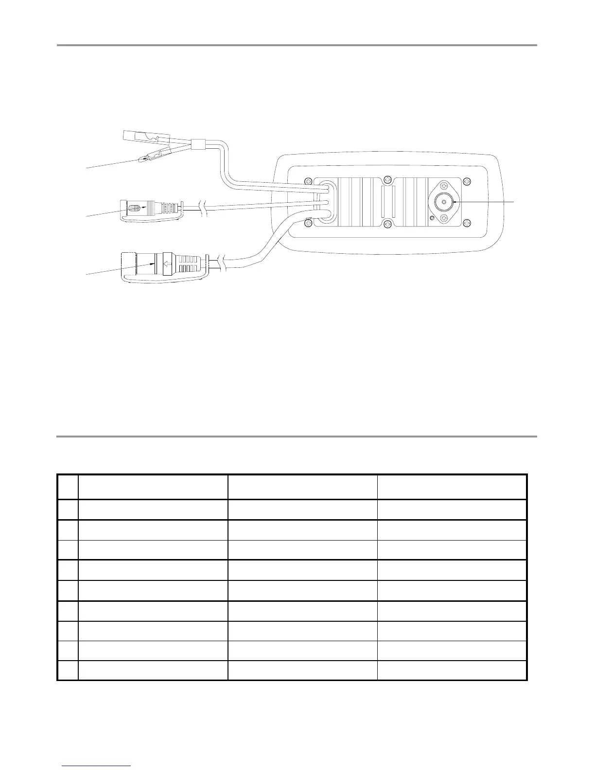
Connect the Radio Cables - Rear view of base unit
1. VHF Antenna connection. (Antenna is not supplied.)
2. Combined power and speaker cable. The end of the power cable splits in two:
BLACK. Earth. Connect to the (-) NEGATIVE battery terminal.
RED. Power. Connect to the (+) POSITIVE battery terminal. Check that a 10A fuse is installed on
this power cable, close to the battery.
3. External speaker cable.
4. GPS connector cable.
7-8 Connecting the Radio
There are three sockets at the rear of the radio, as shown. The combined power & speaker socket and
the GPS socket have short connectors already in place but further electrical wiring is required at the
rear of the radio.