Chapter 3
19
all later issues the additional RAM was housed directly onboard the main PCB). If a
daughter board is not visible but three thick tracks with about a dozen thinner tracks
beyond them running behind the length of the expansion bus can be seen then the
Spectrum is an issue 1 (all subsequent models have ICs present here instead).
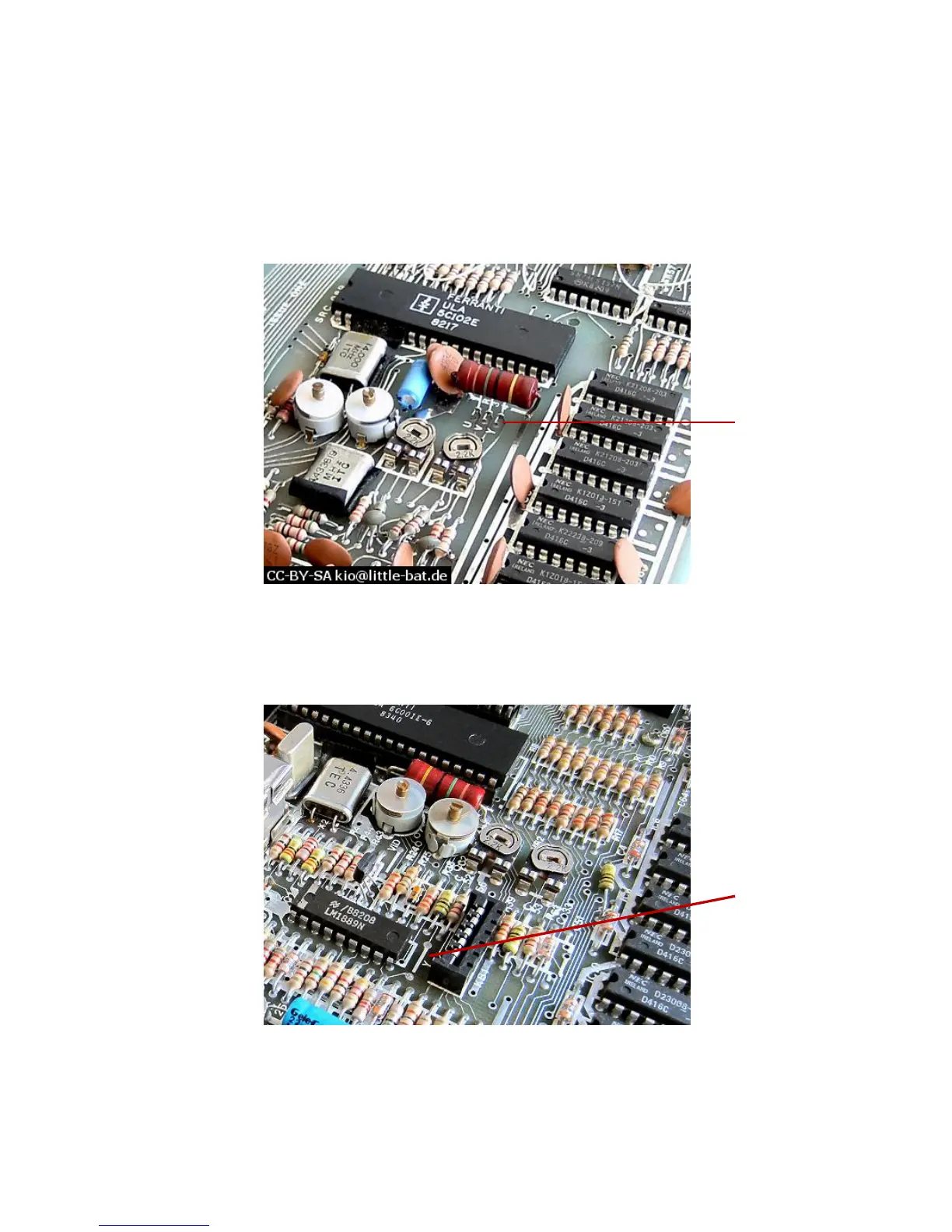
The location to fit the wire link inside an issue 1 Spectrum is shown in the following
photograph:
Luminance wire link position in issue 1 Spectrum
The location to fit the wire link inside an issue 2 Spectrum is shown in the following
photograph:
Luminance wire link position in issue 2 Spectrum
In both cases, the wire link should be fitted between the two holes marked with a
white line and labelled ‘Y’.