Wiring of a SPECTRA / ZX Interface 1 RS232 cable
Note that the screen connection should be made as this will significantly improve the
cable’s resilience to interference. A typical RS232 cable may be up to 15m in length.
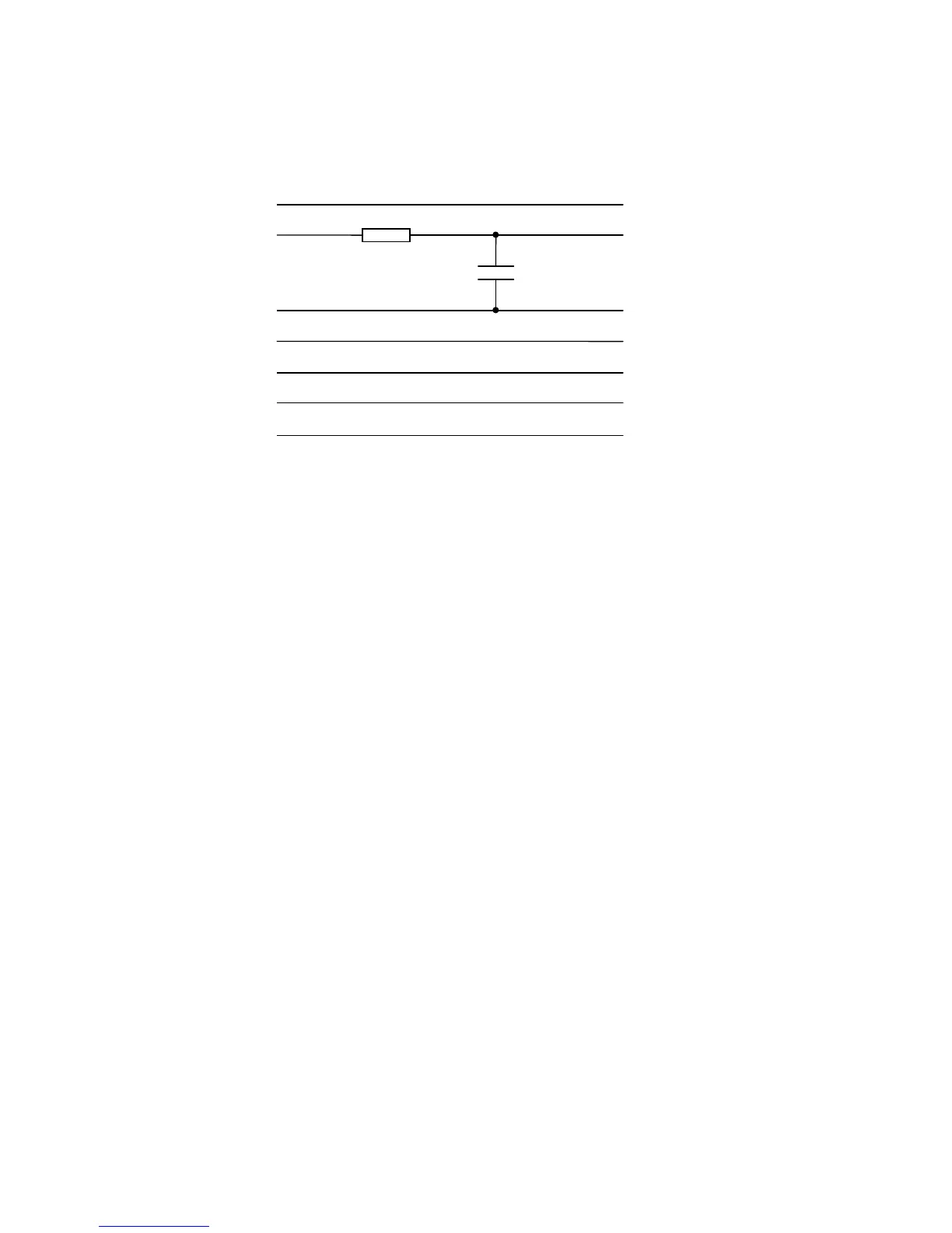
The cable should include a simple filter circuit consisting of a 1k5 resistor and a 10nF
capacitor. Including the filter circuit creates a standard cable design that can be used
with the RS232 socket of the ZX Interface 1 as well as that of the SPECTRA interface.
The filter circuit is used to minimise the effects of a glitch that occurs on the output
data line from the ZX Interface 1 upon every transmission. The glitch occurs because
the ZX Interface 1 hardware shares the output data line between the Network ports
and the RS232 port and the ROM always reverts back to Network mode after each
RS232 transmission. It is this switching action between Network mode and RS232
mode that causes the glitch.
In general, the two devices connected via an RS232 communications link are referred
to as the data terminal equipment (DTE) and the data communications equipment
(DCE). Normally the DTE would be viewed as the device that requires sending /
receiving of data and the DCE as the device that accepts it or provides it, e.g. a
computer would be a DTE and a modem a DCE. The convention is therefore to label
of all signals with respect to the DTE. The ZX Interface 1 confusingly labels its RS232
socket pins as if it were a DCE, and hence the RX data line is used for sending data
and the TX data line used for receiving data. The SPECTRA interface adopts the
ZX Interface 1 labelling scheme since it reproduces its RS232 functionality.
Note that in RS232, TXD stands for transmit data, RXD for receive data, DTR for data
terminal ready, CTS for clear to send and DSR for data set ready.