Chapter 7
60
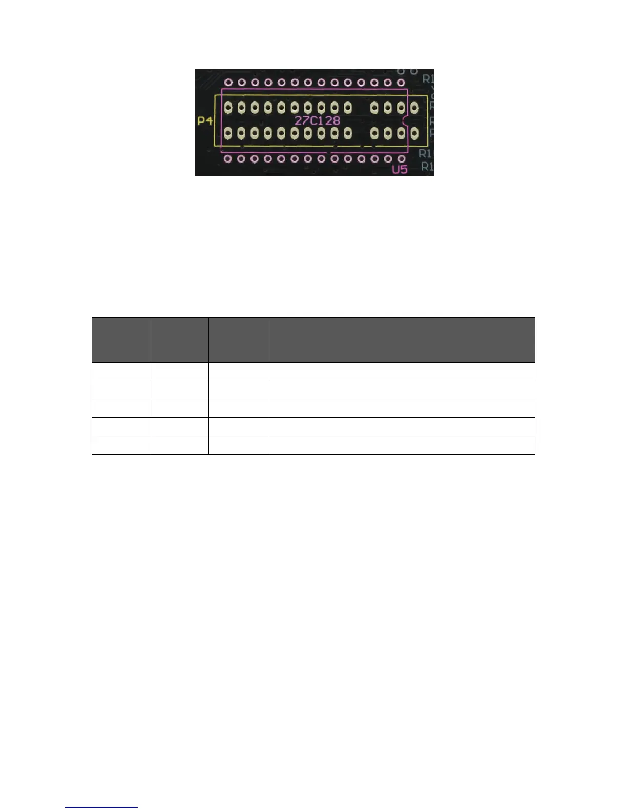
Overlapping ROM socket footprints
The outline labelled U5 can be fitted with a 28-way DIL IC socket to allow an onboard
ROM to be used. The outline labelled P4 can be fitted with a 2 x 15-way edge
connector socket to allow the use of ZX Interface 2 ROM cartridges.
The table below summarises the different ROM modes supported by the SPECTRA
interface:
Summary of supported ROM modes
When an onboard ROM is not present, configuration switch 2 should always be set to
the off position. A ROM cartridge or an onboard ROM should only ever be inserted or
removed while the Spectrum is powered off, otherwise a crash will occur and damage
may result to the hardware. With an external ROM connected and enabled, it is the
state of configuration switch 3 that determines whether the Spectrum’s BASIC ROM
will be overridden or supplemented.
Overriding the Spectrum’s ROM
The Spectrum’s ROM can be overridden by setting configuration switch 3 to the off
position. The SPECTRA interface will automatically detect and enable a ROM cartridge
if one is plugged in, but to use an onboard ROM requires manually enabling it by
setting configuration switch 2 to the on position. Either form of external ROM will
remain enabled even after the Spectrum is reset. If an onboard ROM is fitted but
configuration switch 2 set to the off position then the onboard ROM is disabled and
will lie dormant. If a device connected behind the SPECTRA interface requests access
to the ROM address space then an onboard ROM or a plugged in ROM cartridge will
always be disabled.