EasyManua.ls Logo

Sinclair ZX Spectrum User Manual

Sinclair ZX Spectrum
82 pages
To Next Page IconTo Next Page
To Previous Page IconTo Previous Page
Page #30 background imageLoading...
Page #30 background image
Chapter 4
28
15
14
13
12
11
10
9
8
7
6
5
4
3
2
1
0
Display file:
0
1
0
A1
A0
L2
L1
L0
R2
R1
R0
C4
C3
C2
C1
C0
Attributes file:
0
1
0
1
1
0
A1
A0
R2
R1
R0
C4
C3
C2
C1
C0
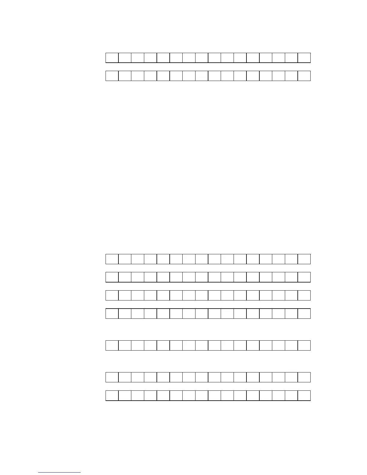
The area number is specified by bits An, the row number within an area by bits Rn, the
pixel line number within a row by bits Ln and the column number by bits Cn. It can be
seen that the lower 8 bits are identical between the display file and the attributes file,
and this approach was used since it simplified the picture generation logic inside the
ULA. Note that the A0 and A1 bits never both hold a value of 1, and thus the display
file and the attributes file can never overlap.
The new attribute modes provided by the SPECTRA interface use an addressing
scheme for the display file that is identical to that used by the standard Spectrum
screen. However, the addressing schemes used for the various display mode attribute
files are different. A relationship between them and the display file can be seen by
examining address lines A8 to A12, which shift by one bit position to the left each time
the vertical colour resolution is doubled. It becomes clear that although the standard
attributes file (row mode) visually appears to be a logical progression, it can actually be
thought of as an extreme case of the ‘odd’ sequence seen in the display file. The
addressing schemes for the new attribute modes are shown below.
15
14
13
12
11
10
9
8
7
6
5
4
3
2
1
0
Display file:
0
1
0
A1
A0
L2
L1
L0
R2
R1
R0
C4
C3
C2
C1
C0
Row mode:
0
1
0
1
1
D
A1
A0
R2
R1
R0
C4
C3
C2
C1
C0
Quad line mode:
0
1
1
0
D
A1
A0
L2
R2
R1
R0
C4
C3
C2
C1
C0
Dual line mode:
0
1
1
D
A1
A0
L2
L1
R2
R1
R0
C4
C3
C2
C1
C0
Single line mode basic / extra colours using single byte colour:
0
1
1
A1
A0
L2
L1
L0
R2
R1
R0
C4
C3
C2
C1
C0
Single line mode basic / extra colours using double byte colour:
Single line area:
0
1
1
D
A0
L2
L1
L0
R2
R1
R0
C4
C3
C2
C1
C0
Dual line area:
0
1
0
1
1
D
L2
L1
R2
R1
R0
C4
C3
C2
C1
C0
The bit denoted by D applies to double byte colour and its action depends upon the
full / half cell bit of the display mode register. In full cell mode and in half cell mode

Table of Contents

Other manuals for Sinclair ZX Spectrum

Question and Answer IconNeed help?

Do you have a question about the Sinclair ZX Spectrum and is the answer not in the manual?

Sinclair ZX Spectrum Specifications

General IconGeneral
ProcessorZilog Z80A
Clock Speed3.5 MHz
RAM16KB or 48KB
ROM16KB
Graphics256 x 192 resolution
Sound1-channel beeper
StorageCassette tape
InputKeyboard
Power9V DC
Release Year1982
DisplayTV via RF modulator
PortsExpansion, RF
Colors15 (8 colours with two levels of brightness each, plus black)

Summary

Introduction to the SPECTRA Interface

SPECTRA Interface Features Overview

Details the core features including SCART, sound, display modes, joystick, RS232, ROM, reset, and expansion bus.

Setting Up the SPECTRA Interface

Connection Procedure

Step-by-step guide to connect the interface to the Spectrum and TV for initial use.

Connection Order

Explains how to connect multiple peripherals to avoid ROM conflicts and ensure proper operation.

SCART Connection Guide

Advanced Display Modes

Attribute Mode Overview

Introduces display formats, colour resolutions, and attribute modes for enhanced graphics.

Display Mode Register Control

Explains the 8-bit register used to select and control new display modes.

Joystick Socket Functionality

Kempston Joystick Compatibility

Explains the Kempston socket, its input port, and how to read joystick input.

RS232 Serial Port

RS232 Socket and Cable Wiring

Details the RS232 port, pinout, and custom cable requirements for serial communication.

ROM Support and Extensions

Reset Button and Expansion Bus

Appendix C: Troubleshooting Guide

Common Display and Connectivity Issues

Lists problems like no picture, signal indicator issues, and SCART connection problems.

Peripheral and Mode Conflicts

Addresses issues with display modes, other peripherals, and RS232/joystick conflicts.

Related product manuals