Chapter 4
31
just one byte or separately in two. The interpretation of the attribute byte(s) also
depends upon the state of the full / half cell bit of the display mode register.
A shorthand notation can be used to specify each attribute mode and consists of the
attribute pixel size (width x height) followed by two letters that indicate the colour
mode. The attribute width indicates full cell (8 pixels) or half cell (4 pixels) mode, and
the attribute height indicates row (8 pixels), quad line (4 pixels), dual line (2 pixels) or
single line (1 pixel) mode. The colour mode letters indicate single (S) or double (D) byte
colour, and basic (B) or extra (E) colours. The range of attribute modes, along with the
interpretation of their attribute byte(s), are summarised below. Each mode is described
afterwards in further detail.
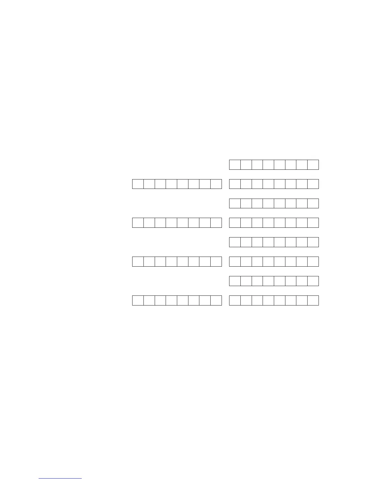
The purpose of each bit in the attribute bytes is denoted by labels F, B, I or P to
indicate whether it defines flash, bright, ink or paper respectively. Subscripts of I and P
indicate that the bit applies only to the ink pixels or only to the paper pixels
respectively. Subscripts of L and R indicate that the bit applies only to the left half or
only to the right half of the attribute cell respectively. Subscripts of g, r and b indicate
the bit specifies the green, red and blue components of the colour respectively. Where
two bits appear within an attribute byte for a single colour component, the right most
bit defines the least significant bit of the colour. A ‘–’ indicates that the bit is available
for use by a program. An ‘*’ indicates the intended purpose of the bit but due to a lack
of resources the SPECTRA interface is unable to support this functionality. In such
cases, the bit should always be set to 0 to ensure forwards compatibility with any
future version of the SPECTRA interface.