EasyManua.ls Logo

Sinee EA180 Series User Manual

Sinee EA180 Series
116 pages
To Next Page IconTo Next Page
Page #1 background imageLoading...
Page #1 background image
EA180 Series Servo Drive Users Manual
1
Introduction
Thank you for choosing EA180 Series Servo Drives!
File No.: 31010184
Release Date: 2020/06
Version: 100
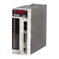
EA180 series servo drives are high-performance medium and small power AC servo units
developed by SINEE. This series of products adopt advanced DSP chips for motor control, large-scale
field programmable gate array (CPLD/FPGA) and PIM power module, and features high integration,
small size, perfect protection and high reliability. The optimized PID control algorithm enables
accurate full-digital control of torque, position and speed to achieve high precision and fast response. It
provides advanced functions such as rigid selection, real-time automatic gain setting, automatic
resonance suppression, etc. In addition, the products have rich digital and analog interfaces and
support MODBUS communication protocol to facilitate networking. The two sub-series respectively
support motors using 2500 PPR incremental pulse encoders or 17-bit incremental magnetic encoders,
Tamagawa's 17-bit incremental photoelectric encoders and 23-bit absolute photoelectric encoders to
meet different requirements on cost and performance. The products can be widely used in automation
fields such as numerical control machine tools, printing and packaging machinery, textile machinery,
robots, automatic production lines, etc.
The EA180 series servo drives are also available in three models supporting EtherCAT bus
(EA180E), CANopen bus (EA180C) and PROFINET bus (EA180P).
We have been committed to the continuous improvement of products and product
information. Therefore, the information provided by us is subject to change without prior notice.
For the latest changes and more information, please visit www.sineedrive.com.

Table of Contents

Other manuals for Sinee EA180 Series

Questions and Answers:

Sinee EA180 Series Specifications

General IconGeneral
SeriesEA180
CategoryServo Drives
Control ModeTorque, Speed, Position
Communication InterfaceRS485, CANopen
Protection FeaturesOver-voltage, Under-voltage, Over-current, Overload, Overheating, Short circuit

Summary

Introduction

Safety Precautions

Before Installation

Safety guidelines and warnings before installing the servo drive.

During Installation

Safety guidelines and warnings during the installation process.

Wiring Safety

Crucial safety instructions for electrical wiring procedures.

Power-On Safety

Pre-power-on checks and post-power-on precautions for safe operation.

Operation and Maintenance Safety

Safety measures during operation and maintenance, including specific hazards.

General Precautions

Important considerations like component handling, disposal, and environmental factors.

Maintenance and Inspection

Notes for Maintenance and Inspection

Key points and notes regarding the maintenance and inspection procedures.

Inspection Items and Frequencies

Details on inspection items and their recommended frequencies for normal use.

Product Information

Unpacking and Initial Checks

Steps to verify product integrity and completeness after unpacking.

EA180 Servo Drive Details

Information on drive model, nameplate, parts, and block diagram.

Servo Motor Information

Servo motor specifications, model descriptions, and nameplate details.

Model Compatibility and Cables

Tables for matching servo drives and motors, and specifications for associated cables.

Installation

Installation Notes and Environment

Guidelines for installation, storage, and environmental conditions.

Servo Drive Installation Details

Direction, space, cooling, grounding, and mounting for the servo drive.

Servo Motor Installation Details

Guidelines for motor installation, including schematic diagrams.

Electrical Protection and Filtering

Recommendations for circuit breakers, fuses, braking resistors, and EMI filters.

Wiring

Peripheral and Main Circuit Connections

Wiring for peripherals, main circuit terminals, and power supply.

Encoder and Control Signal Wiring

Wiring details for encoder signals and CN4 control signals.

Communication, Analog, and Brake Wiring

Wiring for communication, analog outputs, and motor brakes.

Standard Wiring Diagrams

Overall wiring diagrams for position, speed, and torque control modes.

Display and Operation

Display, Buttons, and Operating Modes

Overview of the drive's display, buttons, and operating modes.

Drive Modes and Navigation

Details on initialization, status monitoring, parameter monitoring, and setting modes.

Function Modes and Operations

Explanation of changed parameter, warning/alarm, and auxiliary function modes.

Auxiliary Function Operations

Detailed list and description of auxiliary functions (AF-00 to AF-16).

Trial Run

Drive Power-On and Inspection

Pre-power-on checks and timing sequences for safe drive startup.

Trial Run Procedures

Steps for setting JOG parameters and performing JOG operations.

Servo Enable Methods

Different ways to enable the servo drive for operation.

Adjustment

Control Mode Block Diagrams

Block diagrams for position, speed, and torque control modes.

Gain Adjustment Overview

Purpose, modes, functions, steps, and real-time auto gain adjustment.

Inertia Identification and Resonance Suppression

Offline inertia identification, real-time gain adjustment, and mechanical resonance suppression.

Manual Gain Adjustment and Compensation

Manual gain adjustment, feedforward, friction compensation, and PDFF control.

Function Parameter Table

Parameter Definitions and Groups

Definitions of parameter groups (d0, d1, d2) and their attributes.

Control Parameter Groups (P0-P9)

Detailed tables for P0 (Basic Settings) through P9 (Multi-position) parameters.

Tuning and System Parameter Groups

Tables for gain tuning, vibration suppression, I/O, communication, extended functions, and motor parameters.

Warning, Alarm, and Troubleshooting

Alarm Diagnosis and Troubleshooting

Guide to diagnosing and resolving various alarm codes (Al0xx).

Warning Diagnosis and Troubleshooting

Guide to diagnosing and resolving various warning codes (AlExx, PoT, noT).

Specifications

EA180 Servo Drive Specifications

Electrical, environmental, and functional specifications for the EA180 servo drive.

Servo Motor Specifications and Dimensions

Detailed specifications, parameters, and dimensional drawings for SER and SES servo motors.

Overload Characteristics

Definition, reasons, and graphical representation of servo motor overload characteristics.

Related product manuals