5
HTE302172 19/46
6
7. Push “Set” button to shift the mode from
“Indication” to “Adjust”.
Blinkin
Push “SET”
8. Dial the Setting Encoder in the counterclockwise to reduce
the drive frequency so that the work pieces are discharged smoothly.
Push “Set” button two times to shift the blinking digit
from decimals to units.
Note: In the case of “Model CF” drive unit the stroke must be set for at the maximum of the unit.
Setting Encoder
Dial
9. When the work pieces are discharged smoothly, push the “Save” button
to store the data having been set.
Push “Save” button
Storing
New data is stored
6. Push “Run/Stop” button and run the partsfeeder or linear feeder.
This example shows the partsfeeder is running at the output
voltage 75 % and drive frequency 90 Hz.
Note: When RUN lamp is blinking
see “Alarm by blinking RUN lamp” on the page 8.
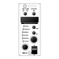
5. Dial “Selection Dial” and select “Frequency”.
Selection Dial
Turning on
Dial
Push Run/Stop
Turning RUN lamp on.
5
HTE302172 20/46
6
4. Push “Set” button to change the mode from
“Indication” to “Adjustment”.
How to set the Stroke on
How to set the Stroke on How to set the Stroke on
How to set the Stroke on
Constant Stroke mode
Constant Stroke modeConstant Stroke mode
Constant Stroke mode
3. Dial “Selection Dial” to select “Function”.
1. On the beginning, “Stroke” is set on the “Auto-tuning” mode.
See “How to set the stroke on the auto-tuning mode”.
2. Push “Auto Freq” button more than three seconds
and change the mode from auto-tuning to constant stroke.
Push button
AUTO FREQ AUTO FREQ
Selection Dial
Turning on
Dial
Push button
Blinking
After setting the “Frequency Range”, set the stroke following the procedure below.
Put some work pieces in the bowl or chute and set the stroke so that they are discharged
smoothly on the track.
Initial Setting
Initial SettingInitial Setting
Initial Setting
-Continued-
push more than three seconds
 Loading...