5
HTE302172 23/46
6
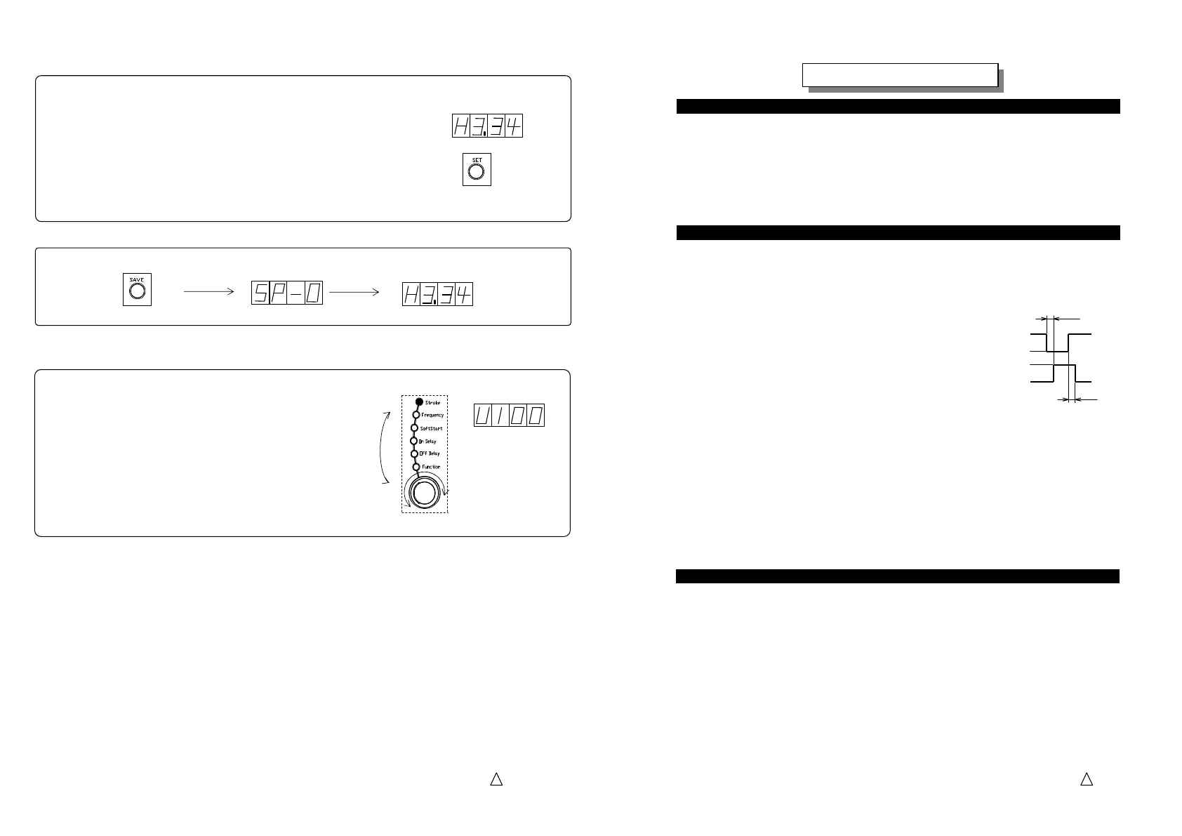
6. Push “Save” button to store the data having been set.
Push
Storing
Converted
7. Dial the selection dial and select the “Stroke”.
Make sure that “100” appears on the display.
In the case that the stroke has been set on every combination
No. 1, 2 and 3 all settings are converted with the scaling
coefficient calculated above.
There is no need to reset them again.
Selection Dial
Dial
Turning on
5. Push and hold the “Set” button more than three seconds and the minimum scaling coefficient that
converts the present stroke data into just “100” appears on the display.
The coefficient is calculat
ed automatically in the machine.
Example: Present stroke data “30.0” percent per the output voltage
After it converted “100” percent per the controllable range
The coefficient calculated 100/30.0=3.34
Push and hold more than 3 seconds
The third decimal place is rounded up.
5
HTE302172 24/46
6
On the ‘Keylock’ function code, the window shows ‘Loc0’ as the default. Then select
‘Loc1’ to make keylock effective and push ‘SAVE’ button to fix the setting.
Under the keylock condition, push ‘SET’ button and then the window shows ‘Loc’.
Under the ‘Loc’ condition, the preset data are fixed and the controller never be
initialized. If you want to change the preset data, release the keylock with setting up
‘Loc0’.
When work pieces discharged are full on all the length of the chute the partsfeeder must
stop automatically, that is called “Overflow” function.
To set the overflow function follow the procedure below.
Note: See the next article as for the connection
diagram of the overflow sensors.
Select “On Delay” of “Off Delay” with
the Setting Dial and set the delay time.
Adjustable time is 0.2 to 60 seconds.
The default is set for 0.2 seconds.
a. “On delay”
On delay time is a duration the partsfeeder restarts after the overflow sensor signals
“OFF” or close contacts refrained from “ON” or open contacts. Recommended duration
“T1” is 0.2 to 0.5 seconds generally.
b. “Off delay”
Off delay time is a duration the partsfeeder stops after the overflow sensor signals
“ON” or open contacts sensing work pieces on the track. Recommended duration “T2”
is 1.0 to 1.2 seconds generally.
Ramp up time of a partsfeeder or linear feeder depends on many factors such as the drive
frequency, weight of a bowl or chute, air gap of core and armature, and so on.
If necessary, dial the selection dial to select “Soft Start” and adjust the ramp up time
between 0.2 to 4.0 seconds that is adjustable.
The default is set for 0.5 seconds.
Note: On the auto-tuning mode or constant stroke mode, the soft start ramp up time follows
not always the preset value depending on the characteristic of the drive unit.
To improve it, adjust the “Control Gain G”.
Larger gain makes partsfeeder restart early and smaller gain makes it restart slower.
(Time chart)
T1
T2
On delay
ON
OFF
Running
Stopping
Off delay
Setting of On Delay and Off Delay Time
Setting of On Delay and Off Delay TimeSetting of On Delay and Off Delay Time
Setting of On Delay and Off Delay Time
Setting of Soft Start Ramp
Setting of Soft Start RampSetting of Soft Start Ramp
Setting of Soft Start Ramp
up Time
up Timeup Time
up Time
Additional Function
Additional FunctionAdditional Function
Additional Function
up for Keylock
up for Keylockup for Keylock
up for Keylock
function
functionfunction
function
 Loading...