5
HTE302172
39/46
6
First Checking Item
First Checking ItemFirst Checking Item
First Checking Item
Remedy
RemedyRemedy
Remedy
●Does the resonant frequency of the partsfeeder match
the driving frequency range of
C10-controller?
●Review the function setting.
●Readjust the resonant frequency of the drive
unit with leaf springs
●Is the setting of the drive frequency range correct?
●Review the function setting.
●Is the weight of a bowl or chute too heavy for the drive
unit?
●Reduce the weight with a decrease of thickness
of a bowl or chute.
●Adjust the air gap.
●Is there any fault wiring, confusing polarities, the
stroke sensor and
C10-controller?
●Is the air gap out of the standard width?
●Review the wiring plug connector.
●Narrow the air gap of the core and armature of
the drive unit.
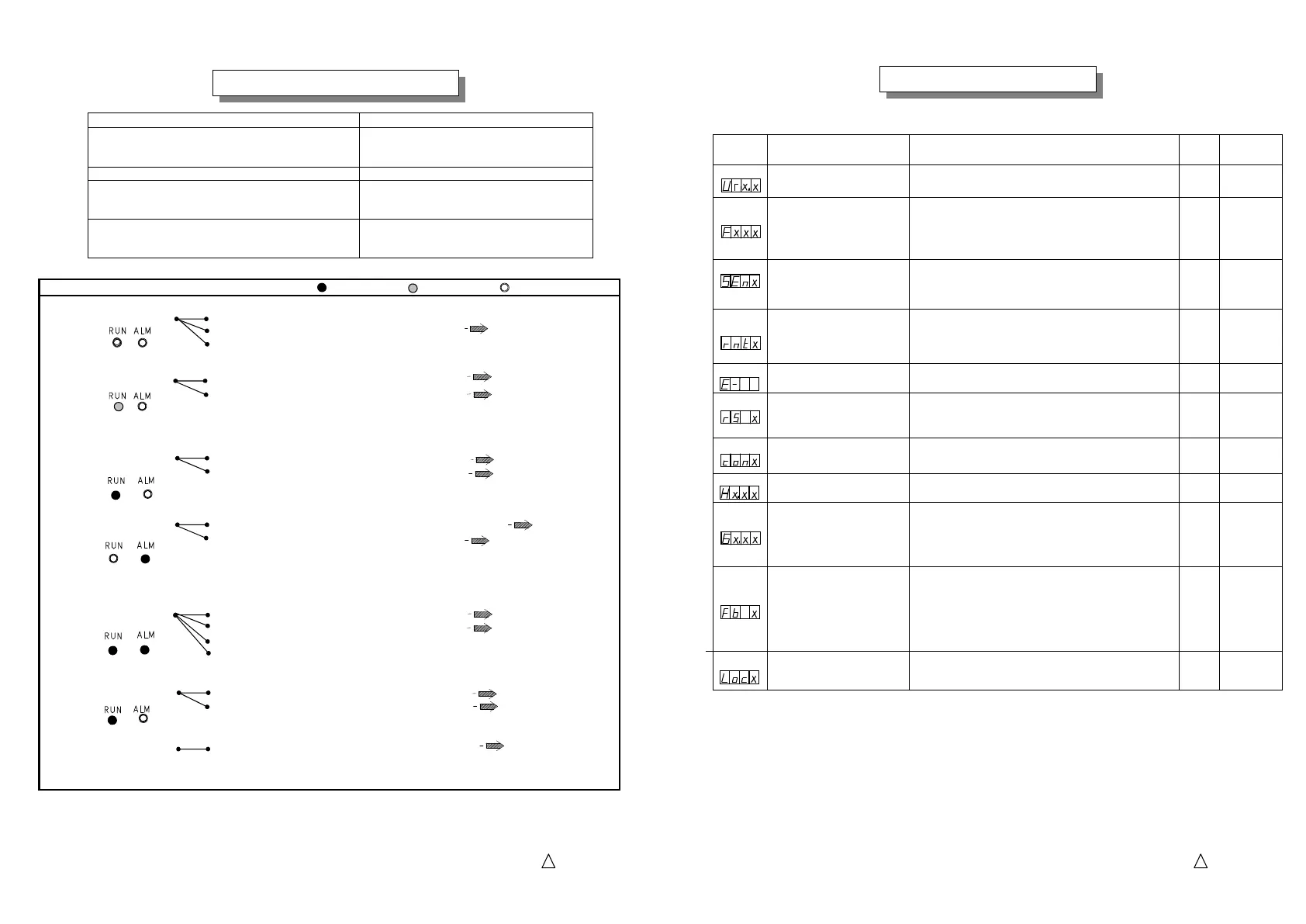
Trouble
TroubleTrouble
Trouble
Checking Item Turning
Checking Item TurningChecking Item Turning
Checking Item Turning
on
onon
on
Biinking
BiinkingBiinking
Biinking
Turning off
Turning off Turning off
Turning off
A. Feeder does not run
1. Fault wiring of power source
2. Low voltage, supply rated voltage
3. Fuse FU1melts down
B. Feeder does not run
1. Stop by the external operation signal
2. Overflow signal is working.
C. Feeder does not run
1. Fault wiring to the feeder/Cable breaks
2. Fault setting of Stroke
D. Feeder does not run
1.
The stroke sensor
is not working, removed or broken lead.
2. Stop by over current protection
2-1. Fault wiring to the feeder/Any short circuit
2-2. Drive frequency range is out of the resonant frequency of the drive unit
2-3. The air gap of the drive unit is too wide
E.
Stroke does not build up
1. Fault setting of Stroke on the panel
2. Too wide air gap of the drive unit
3. Fault function setting for the Stroke Sensor
4. Feeder provides a bowl out of the specification
F. Stroke fluctuates
1. Fault wiring the shield cable and plug connector
2. Loose fitting of the bowl
G.
Memory stores no setting
1. You did not store the data before off the power
See page 29
See Manual of the feeder
See page 25
See page 5
See page 9
See page 26
See page 9
See Manual of the feeder
See page 25
See Manual of the feeder
See page 9
Trouble Shooting
Trouble ShootingTrouble Shooting
Trouble Shooting
See page 6
5
HTE302172
40/46
6
Function
Function Function
Function
Code
CodeCode
Code
Name of Function
Name of FunctionName of Function
Name of Function
Applicable Range
Applicable RangeApplicable Range
Applicable Range
Factory
Factory Factory
Factory
Default
DefaultDefault
Default
Remarks
RemarksRemarks
Remarks
Ur
Information on version
Program Version
Ex.
1.0
See page 11
F
Drive frequency range
90:45 to 90Hz(Half-wave)
180:90 to 180Hz(Full-wave)
360:180 to 360Hz (High-frequency)
120:65 to 120Hz(Middle-frequency)
180 See page 14
Sen
Direction of stroke sensor
0: Reverse phase
1: Synchronous phase
2: Automatic setting
0
See page 28
rnt
Remote
0: Panel operation
1: 4-20 mA current control
2: Two-Rate-of-Feed with two external rheostats
0
See page 30
E-
Error code Error Code of arising error
E-
See page 41
rS
Run/Stop by the Panel mode
0: Running and stopping by RUN/STOP button on the panel
1: Power supply runs the feeder ignoring RUN/STOP
button
1
See page 8
con
“P1”, “P2”
0: “P1” and “P2” is open
1: “P1” and “P2” is close
0
See page 29
H
Scaling of the stroke
Scaling coefficient: 1.00 to 5.00
1.00
See page 22
G
Control Gain
Gain Range: 0.01 to 9.00
On the auto-
tuning and constant stroke mode,
adjusting gain improves responsibility and
stability of soft start and etc.
1.00
See page 21
See page 24
Fb
Feedback Gain
0: Normal
1: Fine
In the case frequency range “F360”
the feedback gain is set for “Fine”
automatically.
0/1 See page 17
Loc
Key Lock
0: Lock off
1: Lock on
0 See page 24
Function Table
Function TableFunction Table
Function Table
Function Table
Function TableFunction Table
Function Table
 Loading...