5
HTE302172 25/46
6
Connection of Overflow Connector
Connection of Overflow Connector Connection of Overflow Connector
Connection of Overflow Connector “
““
“Work Sensor
Work SensorWork Sensor
Work Sensor”
””
”
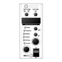
a. C10-controller provides power supply,
DC 12V and maximum 80 mA, to the Overflow sensor
with a plug and socket connector, three cored, on it.
b. Dry contacts or Open Collector,
maximum sink current 10 mA, is connected
to the No.2 and No. 3 core of
the plug connector controls C10-controller.
When No.2 and No.3 core is closed
the partsfeeder stops. When No.2 and No.3 core
is open the partsfeeder runs.
No.2 and No.3 core is open: On Delay setting
No.2 and No.3 core is closed: Off Delay setting
Note
NoteNote
Note: A proximity switch powered by DC with
two cores can not be used.
Connection of Stroke sensor
Connection of Stroke sensor Connection of Stroke sensor
Connection of Stroke sensor “
““
“PF/LF Sensor
PF/LF SensorPF/LF Sensor
PF/LF Sensor”
””
”
Connection diagram is shown on the right side.
Note
NoteNote
Note: The maximum wiring cable length should be 10m.
When the cable is longer than 10m a shield cable
with an excellent high-frequency characteristic must be used.
+12V 0V
SENSOR
1 3
2
OUT
Caution
CautionCaution
Caution: On the soldering of the cable on the cores of a plug connector,
do not mistake the shield for the core nor the core for the shield.
(
No.2
)
Input
Inner Circuit
(
No.1
)+12V
(
No.3
) 0V
+12V
470Ω
+5V
1
2
Shield
Core lead
Dry contacts or Open Collector
Open:Run
Close:Stop
Connection of Overflow and Stroke sensors
Connection of Overflow and Stroke sensorsConnection of Overflow and Stroke sensors
Connection of Overflow and Stroke sensors
Additional Function
Additional FunctionAdditional Function
Additional Function
-Continued-
5
HTE302172 26/46
6
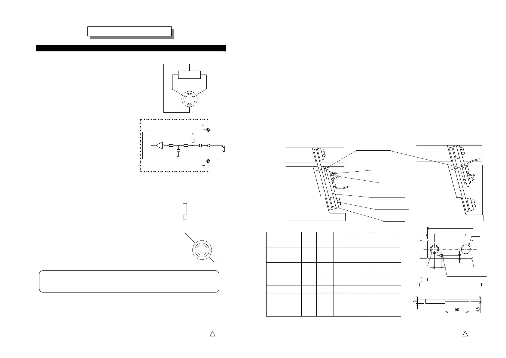
Armature
Base Frame
Mounting of a stroke sensor on a partsfeeder
Mounting of a stroke sensor on a partsfeederMounting of a stroke sensor on a partsfeeder
Mounting of a stroke sensor on a partsfeeder
a.
The stroke sensor must be mounted on in front of a leaf spring with a sensor support.
See the list of the support on the table below that is classified with the model of
the drive unit.
b.
The sensor support is screwed together with the leaf springs with the leaf spring fixing
bolt on the base frame side or bottom without model EA-15 and EA-20.
The supports of model EA-15 and EA-20 must be screwed on the armature or top.
In this case function code “SEn X” must be set for “X=1”. See page 28.
The bolt should be longer than usual by the thickness of the support.
c.
The sensor must be off the leaf spring by 0.5mm and it is called the “air gap”.
d.
Fix the cable with some slack on it to prevent secondary-excited vibration or contact
with any obstacle to break it.
e.
Recommended stroke sensor is: Model EH-110 Proximity sensor by Keyense
Drive Unit W φD L1
L2
Fixing
Direction
EA-15,EA-20
(Previous model)
19 8.5 75 55 Armature
EA-15B 16 7 45 25 Base Frame
EA-20B 19 9 50 30 Base Frame
EA-25,ER-25 19 10.5 80 55 Base Frame
EA-30,ER-30 25 12.5 80 55 Base Frame
EA-38,ER-38 32 16.5 80 55 Base Frame
EA-45,ER-45 32 16.5 80 55 Base Frame
ER-55,65,75 32 16.5 90 60 Base Frame
Size of Sensor support
Spacer
Slack
0.5mm
Air gap
Sensor support
Stroke sensor
Armature
Base Frame
the base frame side
the armature side
See below for ER-55,65,75
M4(
For cable clamp
)
M10 P=1.0
4.5
12
W
L1
L2
4-C1
10
ΦD
 Loading...