5
HTE302172
27/46
6
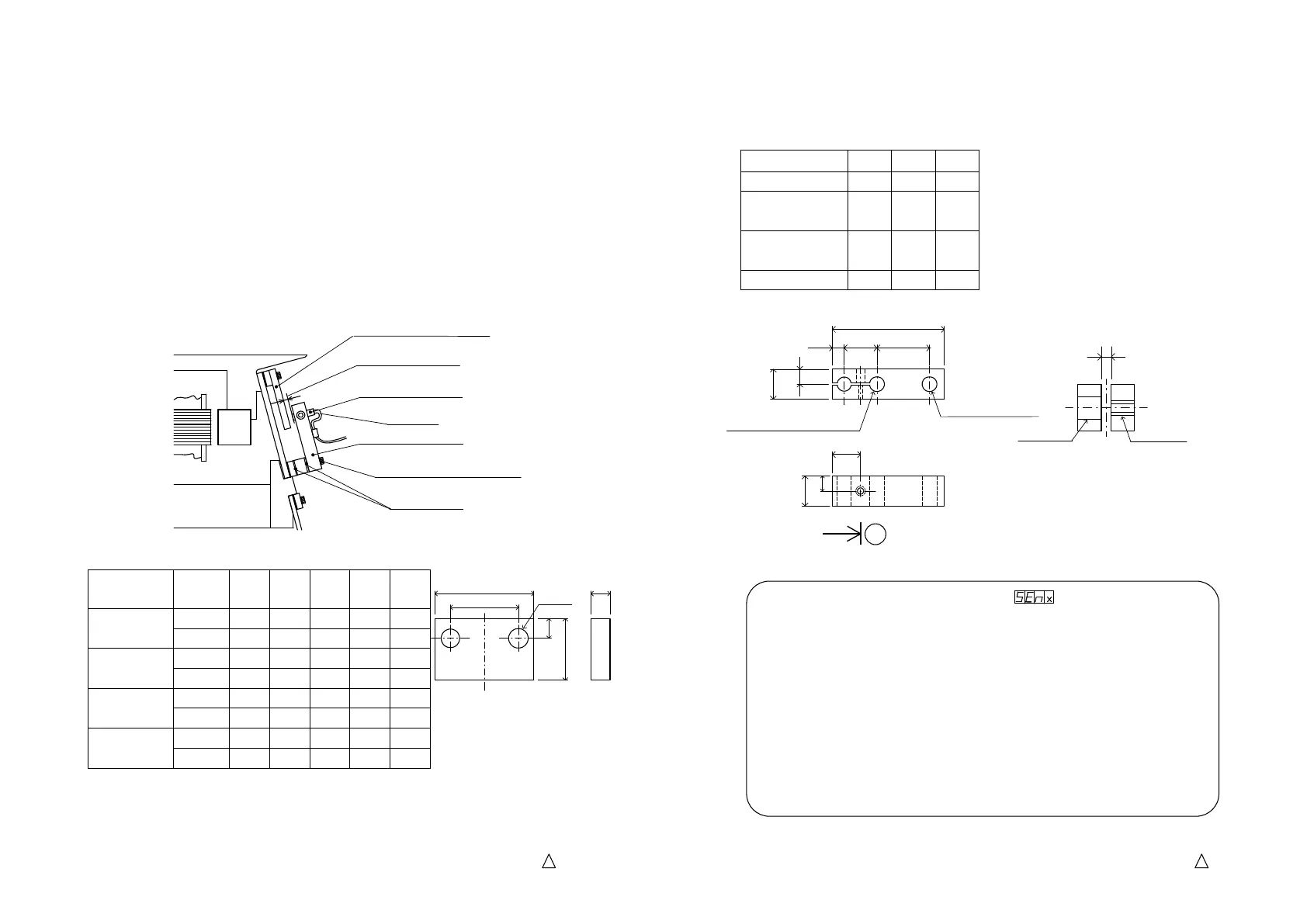
Mounting of Stroke sensor on a linear feeder
Mounting of Stroke sensor on a linear feederMounting of Stroke sensor on a linear feeder
Mounting of Stroke sensor on a linear feeder
a.
Model LFB and DFG series are using leaf springs made of Glass-fiber reinforced plastic
and the proximity sensor does not detect them.
The stainless bar as an object sensed must be mounted on in front of a leaf spring.
The stainless bar is screwed together with the leaf springs with the leaf spring fixing
bolt on the bowl side or top.
b.
The stroke sensor must be mounted on in front of the stainless bar. The sensor support
is screwed together with the leaf springs with the leaf spring fixing bolt on the base
frame side or bottom.
The sensor must be off the bar by 1.0mm and it is called the “air gap”. The width
of the gap changes by the vibration of the drive unit and the change is detected with
the proximity sensor.
The bolt must be longer than usual by the thickness of the support and the bar.
c.
Recommended stroke sensor is “EH-305 Proximity sensor” by Keyense.
d.
Size of the stainless bar / Top and bottom
The table shows model of a linear feeder and the size of the stainless bar.
Drive Unit
Mounted
position
φD
L1
L2
H1
H2
LFB-300
Top 4.5 35 25 15 4
Bottom 4.5 35 25 8 4
LFB-400
LFG-600
Top 5.5 40 28 20 5
Bottom 5.5 40 28 10 5
LFB-550
LFG-750
Top 6.5 45 31 25 6
Bottom
6.5 45 31 12 6
LFG-900
Top 8.5 55 37 30 8
Bottom 8.5 55 37 16 8
6
2-φD
L1
L2
H1
H2
Spacer
Slack
1.0mm
Air gap
Leaf spring fixing bolt
Sensor support
Stroke sensor
Armature
Stainless bar
KEYENCE・・・Model EH-305
5
HTE302172
28/46
6
Size of the stainless bar / Top and bottom
Size of the stainless bar / Top and bottomSize of the stainless bar / Top and bottom
Size of the stainless bar / Top and bottom
The table shows model of a linear feeder and the size of the stainless bar.
Drive Unit φD L1 L2
LFB-300 4.5 35 12
LFB-400
LFG-600
5.5 40 17
LFB-550
LFG-750
6.5 45 22
LFG-900 8.5 50 27
Function
Function Function
Function setting
settingsetting
setting
suits for an arrangement of the Stroke Sensor.
suits for an arrangement of the Stroke Sensor.suits for an arrangement of the Stroke Sensor.
suits for an arrangement of the Stroke Sensor.
It is not necessary to set the Function Code according to the phase of
the air gap on the program version 6 or later.
The phase of the air gap is automatically detected when the auto-tuning of
initial setting is completed.
Manual setting is available by setting the Function Code.
Sen0: The phase is reverse. “Reverse” means when the magnet on the drive unit
pulls down the armature the air gap becomes wide.
Sen1: The phase is synchronous. “Synchronous” means when the magnet on the
drive unit pulls down the armature the air gap becomes narrow.
Sen2: Automatically set
9.5
5
10
A
M3
1.0
-
--
-
Section A-
φ3.5
Through hole on one side
L2 12
L1
4
5
10
φD
Through hole
2-φ5.5
Through hole
(Through)Threading on one
 Loading...