KNIFE
GRINDER
701W51
Grinder
701W51
should be
set
to turn awoy
from
knife at a speed of approximately 2500
revolutions per minute.
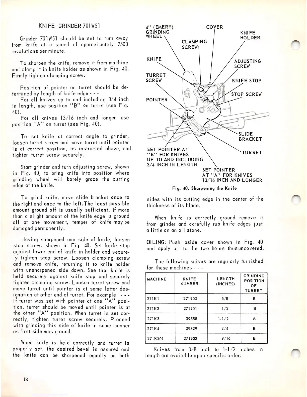
To sharpen the knife,
remove
it
from
machine
and
clamp
it in knife holder as shown in Fig.
40.
Firmly tighten clamping screw.
Position of pointer
on
turret should be de
termined by length of knife edge - - -
For all knives
up
to and including 3/4 inch
in length, use position
**B"
on turret (see Fig.
40).
For all knives 13/16 inch and longer, use
position
"A"
on turret (see Fig.
40).
To
set
knife at correct angle to grinder,
loosen turret screw end move turret until pointer
is at correct position, as instructed above, and
tighten turret screw securely.
Start grinder and turn adjusting screw,
shown
in Fig. 40, to bring knife into position where
grinding
wheel
will barely graze the cutting
edge of the knife.
To grind knife,
move
slide bracket once to
the right and once to the left. The least possible
amount ground off is usually sufficient. If more
than a slight
amount
of the knife edge is
ground
off at one movement, temper of knife may be
damaged permanently.
Having sharpened one
side
of knife, loosen
stop screw, shown in Fig. 40. Set knife stop
against lower end of knife in holder and secure
ly tighten stop screw. Loosen clamping screw
and remove knife, returning it to knife holder
with unshorpened side down. See that knife is
held securely against knife stop and securely
tighten clamping screw. Loosen turret screw and
move turret until pointer is at same letter
des
ignation at other end of turret. For example - - -
if turret was set
with
pointer at one
"A"
posi
tion, turret should be
moved
until pointer is at
the other
"A"
position.
When
turret is
set
cor
rectly, tighten turret screw securely. Proceed
with grinding this side of knife in same manner
as first side was
ground.
When
knife is held correctly
and
turret is
properly set, the desired bevel is assured and
the
knife
can
be
sharpened
equally
on
both
18
4"
(EMERY)
GRINDING
WHEEL
COVER
CLAMPING
SCREW
KNIFE
TURRET
SCREW
POINTER
SET
POINTER
AT
"B"
FOR
KNIVES
UP
TO
AND
INCLUDING
3/4
INCH
IN
LENGTH
KNIFE
HOLDER
ADJUSTING
SCREW
FE
STOP
STOP
SCREW
SLIDE
BRACKET
TURRET
SET
POINTER
AT
"A"
FOR
KNIVES
13/16
INCH
AND
LONGER
Fig. 40. Sharpening
the
Knife
sides
with
its
cutting edge in the center of the
thickness
of
its
blade.
When
knife is correctly ground remove it
from
grinder and carefully rub knife edges just
a
little
on
an
oi
1
stone.
OILING:
Push
aside
cover shown in Fig. 40
and apply oil to the two holes thus uncovered.
The
following
knives are regularly furnished
for
these
machines
- - -
MACHINE
KNIFE
NUMBER
LENGTH
(INCHES)
GRINDING
POSITION
OF
TURRET
271K1
271903
5/8
B
271K2
271901
1/2
B
271K3
39558
1-1/2
A
271K4
39829
3/4
B
271K201
271902
9/16
B
Knives
from
3/8
inch
to
1-1/2
inches
in
length are available upon specific order.