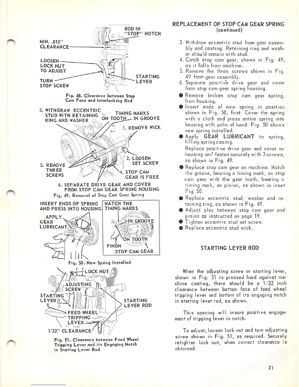
MIN.
.015"
CLEARANCE
LOOSEN
LOCK
NUT
TO
ADJUST
TURN
STOP
SCREW
ROD
IN
"STOP"
NOTCH
STARTING
LEVER
Fig. 48.
Clearance
between Stop
Cam
Face
and Interlocking Rod
3.
WITHDRAW
ECCENTRIC
STUD
WITH
RETAINING
RING
AND
WASHER
.j
V TIMING MARKS
ON
TOOThL-
IN
GROOVE
5.
REMOVE
THREE
SCREWS
1. REMOVE WICK
2.
LOOSEN
SET
SCREW
4.
STOP
CAM
GEAR
IS
FREE
6.
SEPARATE
DRIVE
GEAR
AND
COVER
FROM
STOP
CAM
GEAR
SPRING
HOUSING
Fig. 49.
Removal
of
Stop
Cam
Gear
Spring
INSERT
ENDS
OF
SPRING
AND
PRESS
INTO
HOUSING
APPLY
GEAR
LUBRICANT
MATCH
THE
TIMING
MARKS
1 ;
GROOVE
t^OTH
PINON
STOP
CAM
GEAR
Fig. 50.
New
Spring Installed
V ' I
'•%J
ADJUSTING
_
({
SCREW
STARTING'X)"")^
LEVERIi
Vj
LOCK
NUT.
FEED
WHEEL
TRIPPING
LEVER
V32"
CLEARANCE
Fig. 51. Clearance between Feed
Wheel
Tripping Lever and
its
Engaging Notch
in Starting
Lever
Rod
STARTING
LEVER
ROD
REPLACEMENT
OF
STOP
CAM
GEAR
SPRING
(continued)
3.
Withdraw
eccentric stud
from
gear assem
bly and casting. Retaining ring and wash
er
should
remain
with
stud.
4. Catch stop cam gear, shown in Fig. 49,
as
it
falls
from
machine.
5. Remove the three screws shown in Fig.
49
from
gear assembly.
6. Separate positive drive gear and cover
from
stop
cam
gear
spring
housing.
#
Remove
broken
stop cam gear spring,
from
housing.
# Insert ends of new spring in position
shown in Fig. 50, first. Cover the spring
with a cloth and press entire spring into
housing with palm of hand. Fig. 50 shows
new spring installed.
0
Apply
GEAR
LUBRICANT
to
spring,
filling
spring
casing.
Replace positive drive gear and cover on
housing and fasten securely with
Sscrews,
as shown in Fig. 49.
• Replace stop cam gear on machine. Match
the groove, bearing a timing mark, on stop
cam gear with the gear tooth, bearing a
timing mark, on pinion,
as
shown in
inset
Fig. 50.
• Replace
eccentric
stud, washer and re
taining ring, as shown in Fig. 49.
# Adjust play between stop cam gear and
pinion as instructed on page 19.
• Tighten
eccentric
stud
set
screw,
0 Replace
eccentric
stud wick.
STARTING
LEVER
ROD
When
the adjusting screw or starting lever,
shown in Fig.
51
is pressed hard against ma
chine casting, there should be a 1/32 inch
clearance
between
bottom
face
of
feed
wheel
tripping lever
and
bottom
of its engaging notch
in starting lever rod,
as
shown.
This
spacing will insure positive engage
ment of tripping lever in notch.
To adjust, loosen lock nut and
turn
adjusting
screw
shown
in Fig. 51, as required.
Securely
retighten lock nut,
when
correct clearance is
obtained.
21