FEED
WHEEL
TRIPPING
POINTS
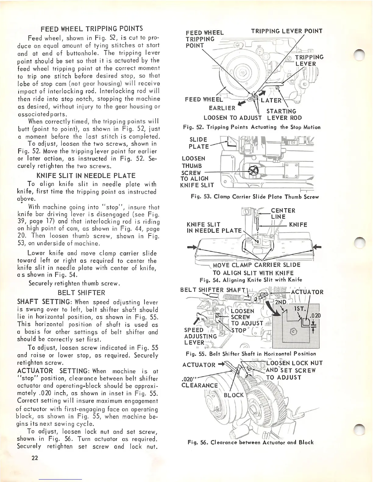
Feed wheel,
shown
in Fig. 52, is cut to pro
duce on
equci
amount
of
tying
stitches at start
and at end of buttonhole. The tripping lever
point
should
be
set so
that
it is
actuated
by
the
feed
wheel
tripping point at the correct
moment
to trip one stitch before desired stop, so that
lobe of stop cam (not gear housing) will receive
impact of interlocking
rod.
Interlocking
rod
will
then ride into stop notch, stopping the machine
as
desired, without injury to the gear housing or
associated parts.
When
correctly timed, the tripping points will
butt (point to point), as shown in Fig. 52, just
a moment before the
last
stitch
is completed.
To adjust, loosen the two
screws,
shown in
Fig. 52.
Move
the tripping lever point for earlier
or later action, as instructed in Fig. 52. Se
curely retighten the two screws.
KNIFE
SLIT
IN
NEEDLE
PLATE
To align knife
slit
in needle plate with
knife, first time the tripping point as instructed
above.
m
With
machine going into
"stop",
insure that
knife
bar
driving
lever is disengaged (see Fig.
39,
page
17)
and
that
interlocking
rod
is
riding
on
high
point of
cam,
as
shown
in Fig. 44, page
20.
Then
loosen
thumb
screw,
shown
in Fig.
53, on
underside
of machine.
Lower
knife and
move
clamp carrier slide
toward left or right as required to center the
knife
slit
in needle plate with center of knife,
Gs
shown
in Fig. 54.
Securely retighten thumb screw.
BELT
SHIFTER
SHAFT
SETTING:
When
speed adjusting lever
is
swung over to left,
belt
shifter
shaft
should
lie
in
horizontal position, as
shown
in
Fig. 55.
This horizontal position of shaft is used as
a basis
for
other settings of belt shifter and
should be correctly
set
first.
To adjust, loosen screw indicated in Fig. 55
and raise or lower stop, as required. Securely
retighten screw.
ACTUATOR
SETTING:
When
machine
is
at
"stop"
position,
clearance
between belt shifter
actuator and operating-block should be approxi
mately .020 inch, as
shown
in inset in Fig. 55.
Correct setting will insure
maximum
engagement
of actuator with first-engaging face on operating
block,
OS
shown in Fig. 55,
when
machine be
gins
its
next sewing cycle.
To adjust, loosen lock nut and set screw,
shown,
in Fig. 56. Turn actuator as required.
Securely retighten
set
screw and lock nut.
22
FEED
WHEEL
TRIPPING
POINT
TRIPPING
LEVER
POINT
FEED
WHEEL
EARLIER
LOOSEN
TO
ADJUST
LEVER
ROD
Fig. 52. Tripping
Points
Actuating
the
Stop Motion
SLIDE
PLATE
LOOSEN
THUMB
SCREW
TO
ALIGN
KNIFE
SLIT
Fig.
53.
Clamp
Carrier
Slide
Plate
Thumb
Screw
KNIFE
SLIT
IN
NEEDLE
PLATE
LATER
TRIPPING
LEVER
CENTER
LINE
^
KNIFE
MOVE
CLAMP
CARRIER
SLIDE
TO
ALIGN
SLIT
WITH
KNIFE
Fig. 54. Aligning Knife Slit with Knife
•"
mm
BELT
SHIFTER
SHAFT!
ACTUATOR
ADJUSTING
LEVER
ACTUATOR
.020"
CLEARANCE
2ND.:^
LOOSEN
SCREW
SPEED
Fig.
55.
Beit
Shifter Shaft in Horizontal
Position
LOOSEN
LOCK
NUT
AND^SET
SCREW
TO
ADJUST
•r/.
BLOCK
to'adjust--
Fig.
56.
Clearance
between
Actuator
and
Block