REAR
EDGE
OF
BLADES
FLUSH
WITH
INSIDE
EDGE
OF
CHECK
LOOSEN
LOCK
NUT'"""^P4
FORWARD
POSITION
CONNECTING
ROD
- ADJUST
STOP
NUT k '
_ AGAINST
\NYLON
WASHER
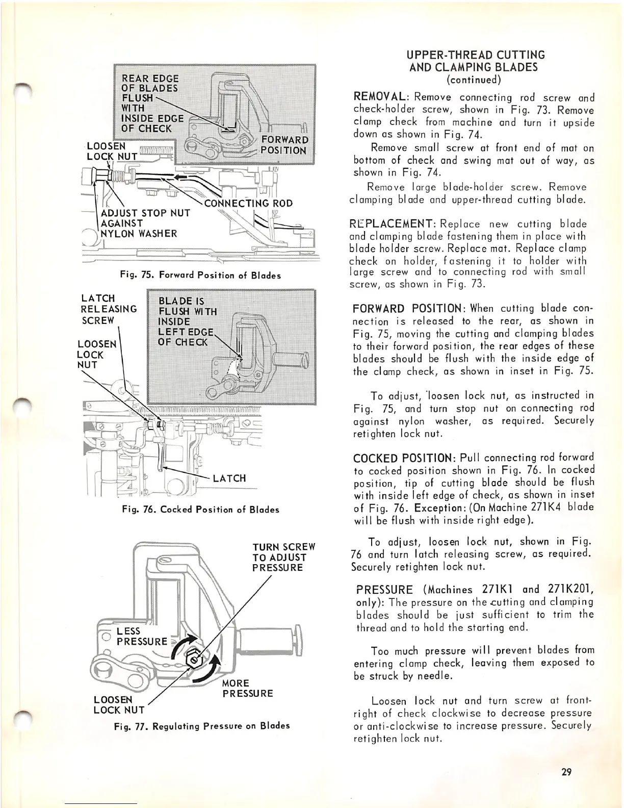
Fig.
75.
Forward
Position
of
Blades
LATCH
RELEASING
SCREW
LOOSEN
LOCK
NUT
BLADE
IS
FLUSH
WITH
INSIDE
LEFT
EDGE
OF
CHECK
mimnmiimmmmMmiinri
LATCH
Fig.
76.
Cocked
Position
of
Blades
PRESSURE
s.
LOOSEN
LOCK
NUT
TURN
SCREW
TO
ADJUST
PRESSURE
MORE
PRESSURE
Fig. 77. Regulating Pressure on Blodes
UPPER-THREAD
CUTTING
AND
CLAMPING
BLADES
(continued)
REMOVAL:
Remove
connecting rod screw and
check-holder
screw,
shown
in
Fig.
73.
Remove
clamp
check
from
machine
and
turn
it upside
down
as
shown
In
Fig. 74.
Remove
small
screw
at
front
end
of
mat
on
bottom of check and swing mat out of way, as
shown in Fig. 74.
Remove large blade-holder screw. Remove
clamping blade and upper-thread cutting blade.
REPLACEMENT:
Replace
new cutting
blade
and clamping blade fastening them in place with
blade holder screw. Replace mat. Replace clamp
check on holder, fastening it to holder with
large screw and to connecting rod with small
screw, as shown in Fig. 73.
FORWARD
POSITION:
When
cutting blade con
nection
is
released
to
the
rear,
as
shown in
Fig. 75,
moving
the cutting and clamping blades
to their forward position, the rear edges of these
blades
should be flush with the inside edge of
the clamp check,
as
shown in inset in Fig. 75.
To adjust, loosen lock nut, as instructed in
Fig.
75,
and
turn
stop nut
on
connecting
rod
against
nylon
washer,
as
required.
Securely
retighten lock nut.
COCKED
POSITION: Pull connecting rod forward
to
cocked
position
shown
in
Fig.
76.
In
cocked
position,
tip
of
cutting
blade
should
be
flush
with inside left edge of check, as
shown
in inset
of
Fig.
76.
Exception:
(On
Machine
271K4
blade
will be flush with inside right edge).
To adjust, loosen lock nut,
shown
in Fig.
76 and
turn
latch releasing screw, as required.
Securely retighten
loc-k
nut.
PRESSURE (Machines 271K1 and 271K201,
only): The pressure on the
Glutting
and clamping
blades should be just sufficient to
trim
the
thread and to hold the starting end.
Too
much
pressure will prevent blades
from
entering
clamp
check,
leaving
them
exposed
to
be struck by needle.
Loosen
lock
nut
and
turn
screw
at
front-
right of check clockwise to decrease pressure
or anti-clockwise to
increase
pressure. Securely
retighten lock nut.
29