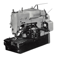
UNDER-THREAD
CUTTING
BLADE
REMOVAL:
Turn machine over
on
its hinges and
remove bobbin case stop screw and bobbin
case
stop,
shown
in
Fig. 73.
Remove
the
two
blade-
holding screws and under-thread cutting blade,
shown in Fig. 72.
REPLACEMENT: Place new cutting blade in
position
shown
in Fig. 72,
with
its cutting edge
between pull-off finger and needle plate. Fasten
blade with two screws, moving blade
as
far as it
will go
toward
left side of machine bed.
Make
certain blade edge is parallel with knife
slit
in
needle plate. Then securely tighten blade-holding
screws.
Replace bobbin
case
stop and screw. Adjust
as
instructed
next.
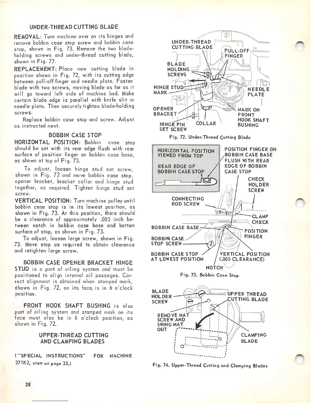
BOBBIN
CASE
STOP
HORIZONTAL POSITION: Bobbin cose stop
should be
set
with its rear edge flush with rear
surface of position finger on bobbin
case
base,
as
shown
at top of Fig. 73.
To adjust, loosen hinge stud
set
screw,
shown
in
Fig. 72
and
move
bobbin
case stop,
opener bracket, bracket collar and hinge stud
together, as required. Tighten hinge stud set
screw.
VERTICAL POSITION: Turn machine pulley until
bobbin case stop is in its lowest position, as
shown in Fig. 73. At this position, there should
be a
clearance
of approximately .005 inch be
tween
notch
in
bobbin
cose
base
and
bottom
surface of stop, as shown in Fig. 73.
To adjust, loosen large screw, shown in Fig.
73.
Move
stop as required to obtain
clearance
and retighten large screw.
BOBBIN
CASE
OPENER
BRACKET
HINGE
STUD is a part of oiling system and must be
positioned to align internal oil passages. Cor
rect alignment is obtained when stamped mark,
5hown in Fig. 72, on
its
face, is in 6
o'clock
position.
FRONT
HOOK
SHAFT
BUSHING
is
also
port of oiling system and stamped mark on
its
face must also be in 6 o'clock position,
as
shown in Fig. 72.
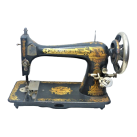
UPPER-THREAD
CUTTING
AND
CLAMPING
BLADES
("SPECIAL
INSTRUCTIONS"
FOR
MACHINE
271K2,
start on page 33.)
28
UNDER-THREAD
CUTTING
BLADE
BLADE
HOLDING
SCREWS
HINGE
STUD
MARK
OPENER
BRACKET
HINGE
PIN
SET
SCREW
COLLAR
Ftg.
72. Under-Thread
Cutting
Blade
HORIZONTAL POSITION
VIEWED FROM
TOP
REAR
EDGE
OF
BOBBIN
CASE
STOP
'
riTSQ
CONNECTING
ROD
SCREW
BOBBIN
CASE
BASE-^-^
-__
BOBBIN
CASE
STOP
SCREW
BOBBIN
CASE
STOP
AT
LOWEST
POSITION
PULL-OFF
FINGER
r?^
NEEDLE
PLATE
mark
ON
FRONT
HOOK
SHAFT
BUSHING
POSITION
FINGER
ON
,BOBBIN
CASE
BASE
FLUSH
WITH
REAR
EDGE
OF
BOBBIN
CASE
STOP
CHECK
HOLDER
SCREW
CLAMP
CHECK
V
POSITION
FINGER
VERTICAL
POSITION
:.005 CLEARANCE)
NOTCH
Fig. 73. Bobbin Case Stop
BLADE
HOLDER
SCREW
[0
rf
REMOVE
MAT
SCREW
AND
SWING
MAT
OUT
UPPER
THREAD
UTTING
BLADE
CLAMPING
BLADE
Fig. 74.
Upper-Thread
Cuttingand
Clamping
Blades