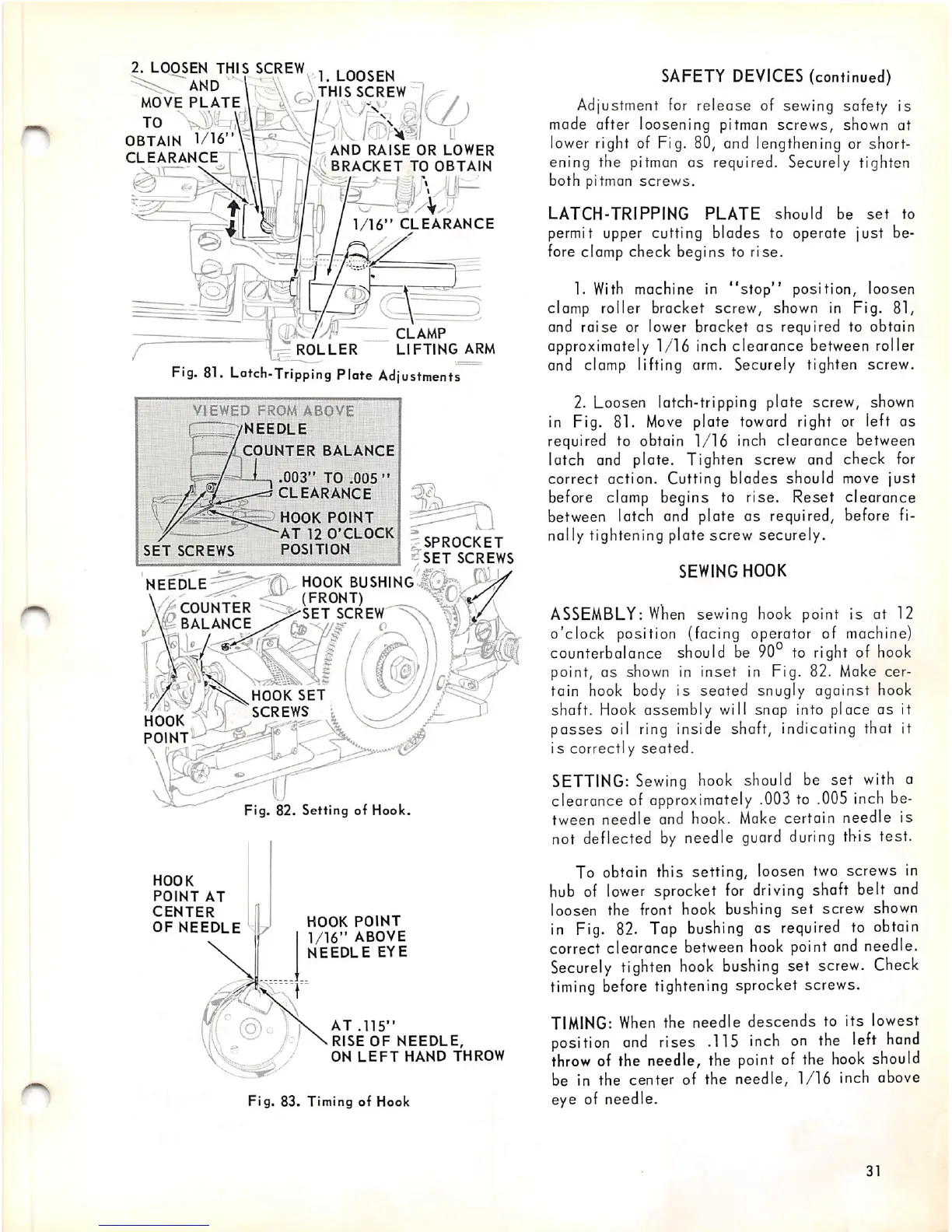
2.
LOOSEN
THIS
SCREW
1.
LOOSEN
7- ) K u
AND
RAISE
OR
LOWER
^BRACKET TO
OBTAIN
J-
- i
AND
MOVE
PLATE
TO
OBTAIN
1/16"
CLEARANCE
TH
S
SCREU
1/16"
CLEARANCE
ROLLER
Fig. 81. Lotch-Tripping Plate Adjustments
CLAMP
LIFTING
ARM
VIEWED
FROM
ABOVE
NEEDLE
COUNTER
BALANCE
SET
SCREWS
NEEDLE
COUNTER
BALANCE
HOOK
POINT
,
.003"
TO
.005"
CLEARANCE
HOOK
POINT
AT
12
O'CLOCK
POSITION
(FRONT)
SET
SCREW
i
HOOK
SET
SCREWS
'V
r?\',
.1
SPROCKET
SET
SCREWS
Fig.
82.
Setting
of Hook.
HOOK
POINT
AT
CENTER
OF
NEEDLE
HOOK
POINT
1/16"
ABOVE
NEEDLE
EYE
AT
.115"
RISE
OF
NEEDLE,
ON
LEFT
HAND
THROW
Fig.
83. Timing of Hook
SAFETY DEVICES (continued)
Adjustment for
release
of sewing safety is
made after loosening pitman
screws,
shown at
lower right of Fig. 80, and lengthening or short
ening the pitman as required. Securely tighten
both pitman
screws.
LATCH-TRIPPING
PLATE
should
be
set
to
permit upper cutting blades to operate just be
fore clamp check begins to rise.
1.
With
machine in
"stop"
position, loosen
clamp roller bracket screw, shown in Fig. 81,
and
raise
or lower bracket
as
required to obtain
approximately 1/16 inch clearance between roller
and clamp lifting arm. Securely tighten screw.
2. Loosen latch-tripping plate screw, shown
in Fig. 81.
Move
plate
toward
right or left as
required to obtain 1/16 inch clearance between
latch and plate. Tighten screw and check for
correct action. Cutting blades should
move
just
before clamp begins to rise. Reset clearance
between latch and plate as required, before fi
nally tightening plate screw securely.
SEWING HOOK
ASSEMBLY:
WVien
sewing
hook
point
is at 12
o'clock position (facing operator of machine)
counterbalance
should
be
90°
to
right
of
hook
point, as shown in inset in Fig. 82.
Make
cer
tain hook body is seated snugly against hook
shaft. Hook assembly will snap into place
as
it
passes
oil ring inside shaft, indicating that it
is
correctly
seated.
SETTING:
Sewing
hook
should
be set
with
a
clearance of
approximately
.003
to
.005
inch
be
tween
needle
and hook. Make
certain
needle
is
not deflected
by
needle
guard
during
this test.
To obtain this setting, loosen two screws in
hub
of
lower
sprocket
for
driving
shaft belt
and
loosen the front hook bushing
set
screw shown
in Fig. 82. Tap
bushing
as
required
to obtain
correct clearance between hook point
and
needle.
Securely
tighten
hook
bushing
set
screw.
Check
timing before tightening sprocket screws.
TIMING:
When
the needle
descends
to
its
lowest
position
and
rises
.115
inch
on
the
left
hand
throw
of the needle, the point of the
hook
should
be in the center of the needle, 1/16 inch above
eye of needle.
31