UPPER
THREAD
CUTTING
AND
CLAMPING
BLADES
(continued)
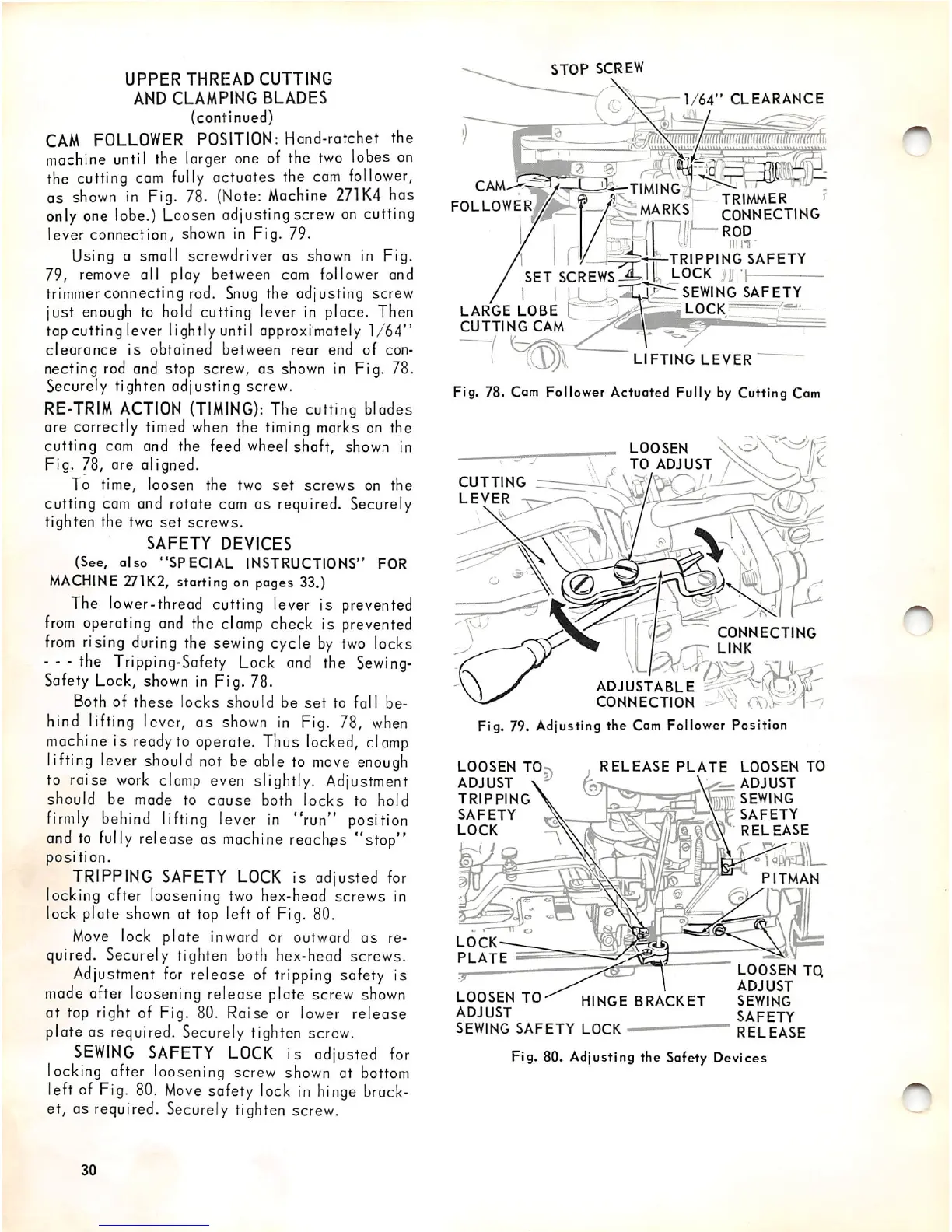
CAM
FOLLOWER
POSITION: Hand-ratchet the
machine
until the larger one of the
two
lobes
on
the cutting
cam
fully
actuates the
cam
follower,
as
shown
In
Fig. 78.
(Note:
Machine
271K4
has
only one lobe.)
Loosen
adjusting screw
on
cutting
lever connection, shown in Fig. 79.
Using G small screwdriver
as
shown in Fig.
79, remove all play between cam follower and
trimmer connecting rod. Snug the adjusting screw
just enough to hold cutting lever in place. Then
top cutting lever lightlyuntil approximately
1/64"
clearance
is
obtained
between
rear
end
of
con
necting rod and stop screw, as shown in Fig. 78.
Securely tighten adjusting screw.
RE-TRIM
ACTION
(TIMING):
The cutting blades
are correctly
timed
when
the
timing
marks on the
cutting cam and the feed wheel shaft, shown in
Fig. 78, are aligned.
To time, loosen the two
set
screws
on
the
cutting cam and rotate cam as required. Securely
tighten the two
set
screws.
SAFETY
DEVICES
(See,
also
"SPECIAL
INSTRUCTIONS"
FOR
MACHINE
271K2, starting on pages 33.)
The lower-thread cutting lever is prevented
from
operating
and
the
clamp
check Is prevented
from
rising during the sewing cycle
by
two
locks
- - - the Tripping-Safety Lock and the
Sewing-
Safety Lock,
shown
in Fig. 78.
Both
of
these
locks
should
be
set
to
fall
be
hind lifting lever,
as
shown in Fig. 78,
when
machine is
ready
to operate. Thus locked,
clomp
lifting lever should not be able to
move
enough
to raise
work
clamp even slightly. Adjustment
should
be
made
to
cause
both
locks
to
hold
firmly
behind lifting lever
in
"run" position
and
to
fully
release as
machine
reaches "stop"
position.
TRIPPING
SAFETY
LOCK
is adjusted for
locking after loosening two hex-head screws in
lock plate
shown
at
top
left of Fig. 80.
Move
lock plate inward or outward
as
re
quired. Securely tighten both hex-head screws.
Adjustment
for
release of tripping safety is
mode
after loosening release plate screw
shown
at top right of Fig. 80. Raise or lower release
plate
OS
required. Securely tighten screw.
SEWING
SAFETY
LOCK
is adjusted
for
locking after loosening screw shown at
bottom
left of Fig. 80.
Move
safety
lock
in
hinge
brack
et, as required. Securely tighten screw.
30
STOP
SCREW
CAM
FOLLOWER
1/64"
CLEARANCE
MARKS
CONNECTING
" 'f/
ROD
—TRIPPING
SAFETY
lock
I
II
I
SET
SCREWS
LARGE
LOBE
CUTTING
CAM
J-irr:
SEWING
SAFETY
LOCK
LIFTING
LEVER
Fig. 78. Cam Follower Actuated Fully by Cutting Cam
CUTTING
LEVER
LOOSEN
TO
ADJUST
TRIPPING
SAFETY
LOCK
LOCK
PLATE
—
LOOSEN
TO
ADJUST
SEWING
SAFETY
LOCK
LOOSEN
TO
ADJUST
/
ADJUSTABLE
CONNECTING
LINK
CONNECTION > V
Fig. 79. Adjusting the Cam Follower Position
RELEASE
PLATE
LOOSEN
TO
ADJUST
\mu
sewing
. . SAFETY
RELEASE
HINGE
BRACKET
^
PITMAN
LOOSEN
TQ
ADJUST
SEWING
SAFETY
RELEASE
Fig. 80. Adjusting the Safety Devices