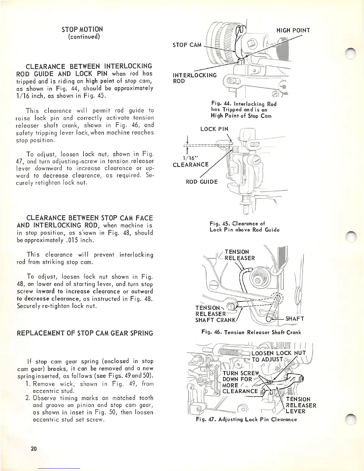
STOP
MOTION
(continued)
CLEARANCE
BETWEEN INTERLOCKING
ROD GUIDE AND LOCK PIN when rod
has
tripped
and
is
riding
on
high
point
of stop
cam,
as
shown
in Fig. 44, should be approximately
1/16
inch, as shown in Fig. 45.
This clearance will permit rod guide to
raise lock pin and correctly activate tension
releaser shaft crank, shown in Fig. 46, and
safety
tripping
lever
lock,
when
machine
reaches
stop
position.
To adjust, loosen lock nut, shown in Fig.
47, and turn adjusting-screw in tension releaser
lever downward to increase
clearance
or up
ward to
decrease
clearance,
as
required. Se
curely retighten lock nut.
CLEARANCE
BETWEEN
STOP
CAM
FACE
AND
INTERLOCKING ROD, when machine
is
in stop position, as shown in Fig. 48, should
be approximately .015 inch.
This clearance will prevent interlocking
rod
from
striking stop cam.
To adjust, loosen lock nut
shown
in Fig.
48, on lower end of starting lever, and turn stop
screw
inward
to
increase
clearance
or
outward
to decrease clearance,
as
instructed in Fig. 48.
Securely re-tighten lock nut.
REPLACEMENT
OF
STOP
CAM
GEAR
SPRING
If stop cam gear spring (enclosed in stop
cam gear) breaks, it can be
removed
and a
new
spring
inserted, as
follows
(see Figs.
49
and
50).
1. Remove wick, shown in Fig. 49,
from
eccentric
stud.
2. Observe timing marks on matched tooth
and groove on pinion and stop
com
gear,
as
shown in inset in Fig. 50, then loosen
eccentric
stud
set
screw.
20
STOP
CAM
INTERLOCKING
ROD
HIGH
POINT
Fig. 44. Interlocking
Rod
has Tripped and is on
High
Point
of Stop Cam
LOCK
PIN
llf;®
a
CLEARANCE
ROD
GUIDE
Fig.
45.
Clearance
of
Lock
Pin
above
Rod
Guide
,,
TENSION
^RELEASER
TENSION
RELEASER
SHAFT
CRANK
Fig.
46.
Tension
Releaser
Shaft
Crank
SHAFT
QLOOSEN
LOCK
NUT
TO
ADJUST,
II f
TURN
SCREW,
DOWN
F0R'/,\2p^
MORE
CLEARANCE
"
Fig.
47.
Adjusting
Lock
Pin
Clearance
TENSION
'
\releaser
LEVER