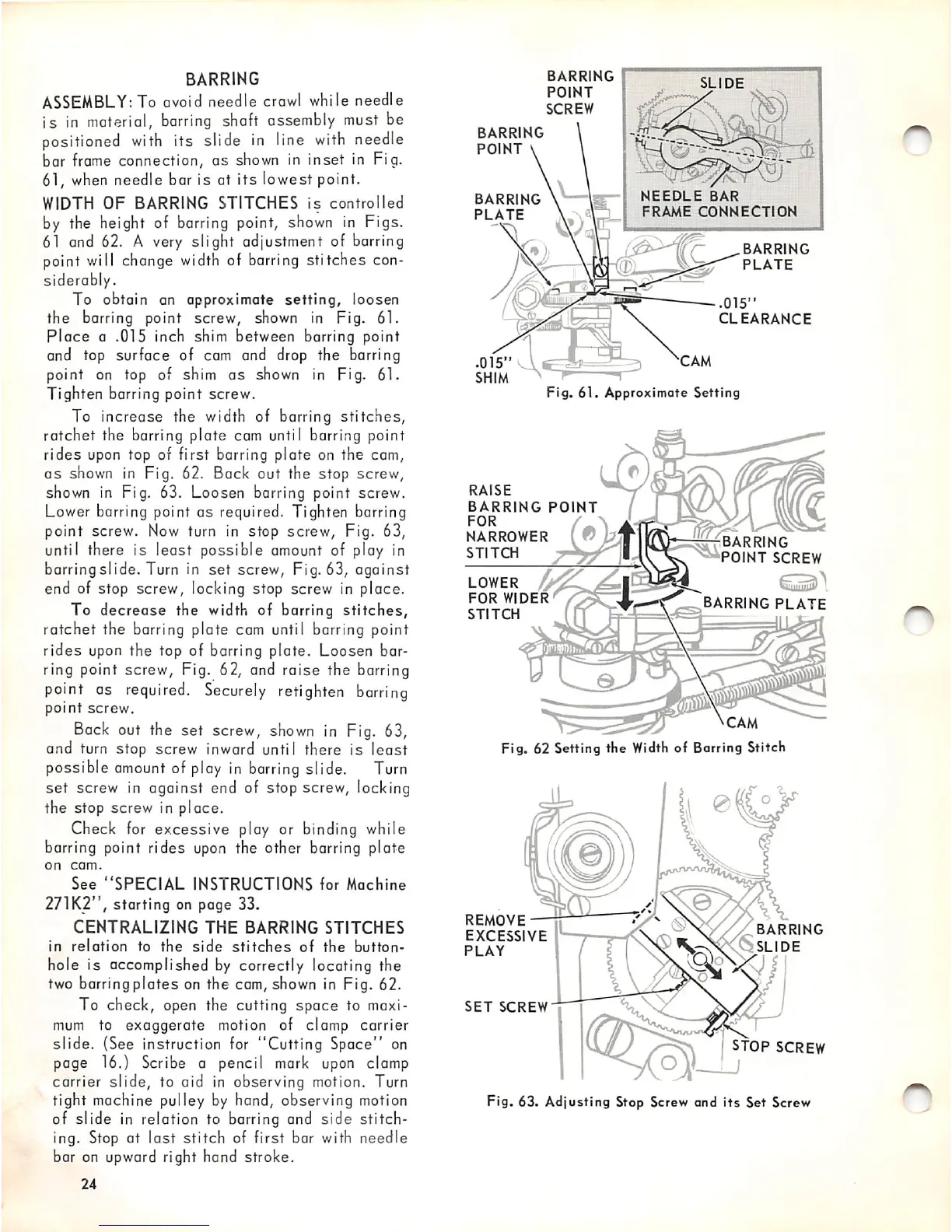
BARRING
ASSEMBLY:
To avoid needle
crow!
while needle
is
in
material,
barring
shaft assembly must be
positioned
with
its slide
in
line
with
needle
bar
frame
connection, as
shown
in inset in Fig.
61,
when
needle bar is at
its
lowest point.
WIDTH
OF
BARRING
STITCHES
is
controlled
by the height of
barring
point,
shown
in Figs.
61 and 62. A very slight adjustment of barring
point will change
width
of barring stitches con
siderably.
To obtain an approximate
setting,
loosen
the barring point screw, shown in Fig. 61.
place
a .015 inch shim between barring point
and top surface of cam and drop the barring
point on top of shim
as
shown in Fig. 61.
Tighten barring point screw.
To increase the width of barring
stitches,
ratchet the barring plate cam until barring point
rides upon top of first barring plate on the cam,
as
shown in Fig. 62. Back out the stop screw,
shown in Fig. 63. Loosen barring point screw.
Lower barring point as required. Tighten barring
point screw. Now turn in stop screw. Fig. 63,
until there is least possible amount of play in
barringslide. Turn in
set
screw, Fig. 63, against
end of stop screw, locking stop screw in place.
To
decrease
the width of barring
stitches,
ratchet the barring plate cam until barring point
rides
upon
the top of barring plate. Loosen bar
ring point screw. Fig. 62, and raise the barring
point
as
required.
Securely
retighten
barring
point
screw.
Back
out the set screw,
shown
in Fig. 63,
and turn stop screw inward until there is
least
possible
amount
of
ploy
in
barring
slide.
Turn
set
screw in against end of stop screw, locking
the stop screw in place.
Check for
excessive
play or binding while
barring point rides
upon
the other barring plate
on
com.
See
"SPECIAL
INSTRUCTIONS
for
Machine
271K2", starting on page 33,
CENTRALIZING
THE
BARRING
STITCHES
in
relation
to
the
side
stitches
of
the
button
hole is accomplished
by
correctly locating the
two barring
plates
on the cam, shown in Fig. 62.
To check, open the cutting
space
to maxi
mum
to exaggerate motion of clamp carrier
slide. (See instruction
for
"Cutting Space" on
page 16.) Scribe a pencil
mark
upon
clamp
carrier slide, to aid in observing motion. Turn
tight machine pulley by hand, observing motion
of
slide
in relation to barring and
side
stitch
ing. Stop at
last
stitch
of first bar with needle
bar on upward right hand stroke.
24
BARRING
POINT
SCREW
BARRING
POINT
BARRING
PLATE
SLIDE
\ V - V
VA'
- - C
NEEDLE
BAR
FRAME
CONNECTION
BARRING
PLATE
.015"
CLEARANCE
.015"
SHIM
Fig.
61.
Approximate
Setting
RAISE
BARRING
POINT
FOR
NARROWER
STITCH
LOWER
FOR
WIDER
STITCH
BARRING
POINT
SCREW
BARRING
PLATE
Fig. 62 Setting the
Width
of Barring Stitch
REMOVE
EXCESSIVE
PLAY
SET
SCREW
BARRING
§
SLIDE
STOP SCREW
Fig. 63. Adjusting Stop Screvr and
its
Set Screw
r^