9. Turn the needle bar crank until it is in the position shown at T3, Fig. 30, to prevent crank from disturbing the
three wick loops in holder U3, Fig. 30 during removal
of
arm shaft.
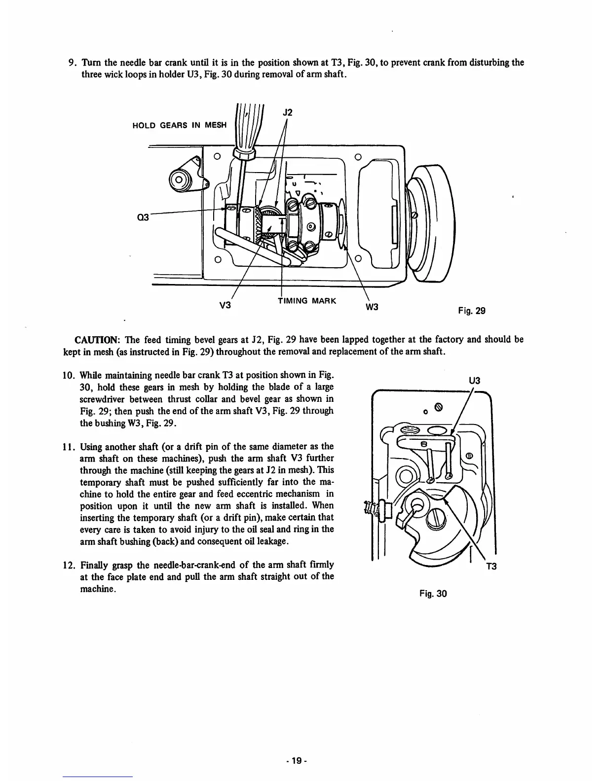
HOLD
GEARS
IN
MESH
[
TIMING
MARK
Fig.
29
CAUTION: The feed timing bevel gears at J2, Fig. 29 have been lapped together at the factory and should be
kept in mesh(asinstructed in Fig.29) throughout the
removal
and replacement
of
the arm shaft.
10.
While
maintaining needle bar crank T3 at position shown in Fig.
30, hold these
gears
in mesh by holding the blade
of
a large
screwdriver between thrust collar and bevel gear as shown in
Fig. 29; then push the end of the arm shaft V3, Fig.29 through
the
bushing W3, Fig.
29.
11. Usinganother shaft (or a drift pin of the same diameter as the
arm shaft on these machines), push the arm shaft V3 further
through the machine (still
keeping
the
gears
at J2 in mesh).This
temporary shaft must be pushed sufficiently far into the ma
chine to hold the entire gear and feed eccentric mechanism in
position upon it until the new arm shaft is installed.
When
inserting the temporary shaft (or a drift pin), make certain that
every care is taken to avoid injury to the oil sealand ringin the
arm shaft bushing (back) and consequent oil leakage.
12. Finally grasp the needle-bar-crank-end of the arm shaft firmly
at the face plate end and pull the arm shaft straight out of the
machine.
3^
-19


 To Next Page