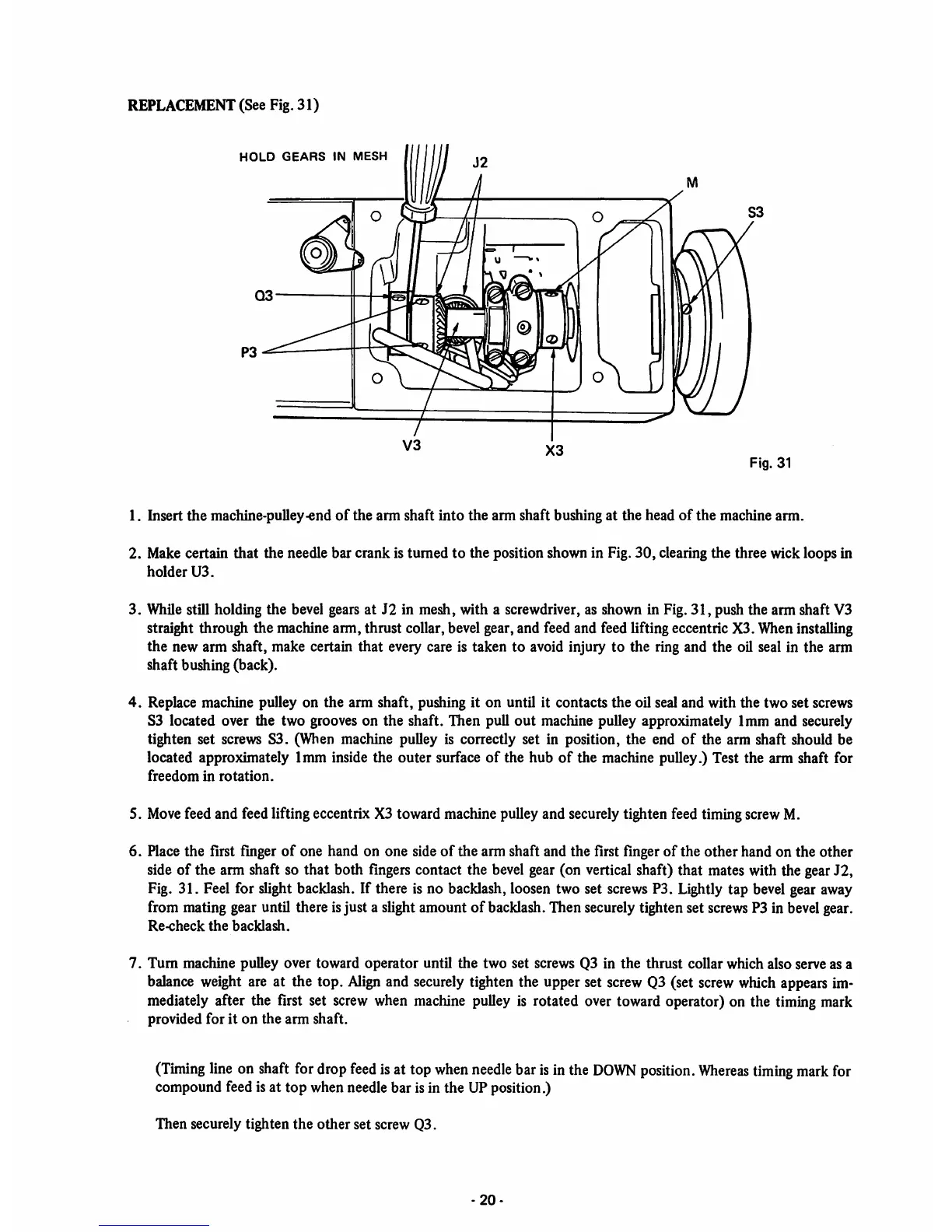
REPLACEMENT (See Fig. 31)
HOLD
GEARS
IN
MESH
[
Fig. 31
1. Insert
the
machine-pulley-end
of
the arm shaft
into
the arm shaft bushing at the head
of
the machine arm.
2. Make certain that the needle bar crank is turned to the position shown in Fig.
30,
clearing the three wick loops in
holder
U3.
3. While still holding the bevel gears at J2 in mesh, with a screwdriver, as shown in Fig.
31,
push the arm shaft V3
straight through the machine arm, thrust collar, bevel gear, and feed and feed lifting eccentric X3. Wheninstalling
the new arm shaft, make certain that every care is taken to avoid injury to the ring and the oil seal in the arm
shaft bushing (back).
4.
Replace machine pulley on the arm shaft, pushing it on until it contacts the oil seal and with the two set screws
S3 located over the two grooves on
the
shaft. Then pull
out
machine pulley approximately 1mm and securely
tighten set screws S3. (When machine pulley is correctly set in position, the end
of
the arm shaft should be
located approximately 1mm inside the outer surface
of
the hub
of
the machine pulley.) Test the arm shaft for
freedom
in
rotation.
5.
Move
feed and feed lifting eccentrix X3 toward machine pulleyand securelytighten feed timingscrewM.
6. Place the first finger
of
one hand on one side
of
the arm shaft and the first finger of the other hand on the other
side of the arm shaft so that both fingers contact the bevel gear (on vertical shaft) that mates with the gearJ2,
Fig. 31. Feel for slight backlash. If there is no backlash, loosen two set
screws
P3. Lightly tap bevel gear away
from mating gear until there isjust a slightamount of backlash.Then securelytighten set screwsP3 in bevelgear.
Re-check
the
backlash.
7.
Turn
machine pulley over toward
operator
until the two set screws Q3 in
the
thrust collar which also serve as a
balance weight are at the top.
Align
and securely tighten the upper set screw Q3 (set screw which appears im
mediately after the first set
screw
when
machine
pulley is rotated over toward operator) on the timingmark
provided for it
on
the
arm
shaft.
(Timing
line
on
shaft
for
drop
feed
isat top
when
needle
barisinthe
DOWN
position.
Whereas
timing
mark
for
compound feed is at top when needle bar is in the UP position.)
Then securely tighten
the
other
set screw Q3.
-20-