© Mar. 2022 5-12 GTTZ10EJ Maintenance Manual
MAINTENANCE
5. Re-connect the cables, connectors and hoses to
the drive motor & reducer assembly.
6. Remove the jack.
4. Check
1. Start the machine.
2. Drive the machine forward and reverse at high
speed to check for malfunctions.
Wheel Support
1. Preparation
UNSAFE OPERATION HAZARD
• Cordon off the test area before the
maintenance is performed.
• Be sure to wear goggles,
protective clothing and gloves.
• The machine must be positioned
on a level, firm surface clear of
obstructions.
• The disassembly, if needed, must
be performed by qualified trained
personnel with power supply
completely off.
BURN AND EJECTION HAZARDS
Before removing the hydraulic
hoses, cool down the hydraulic oil to
room temperature, and slowly loosen
the hose to release the pressure.
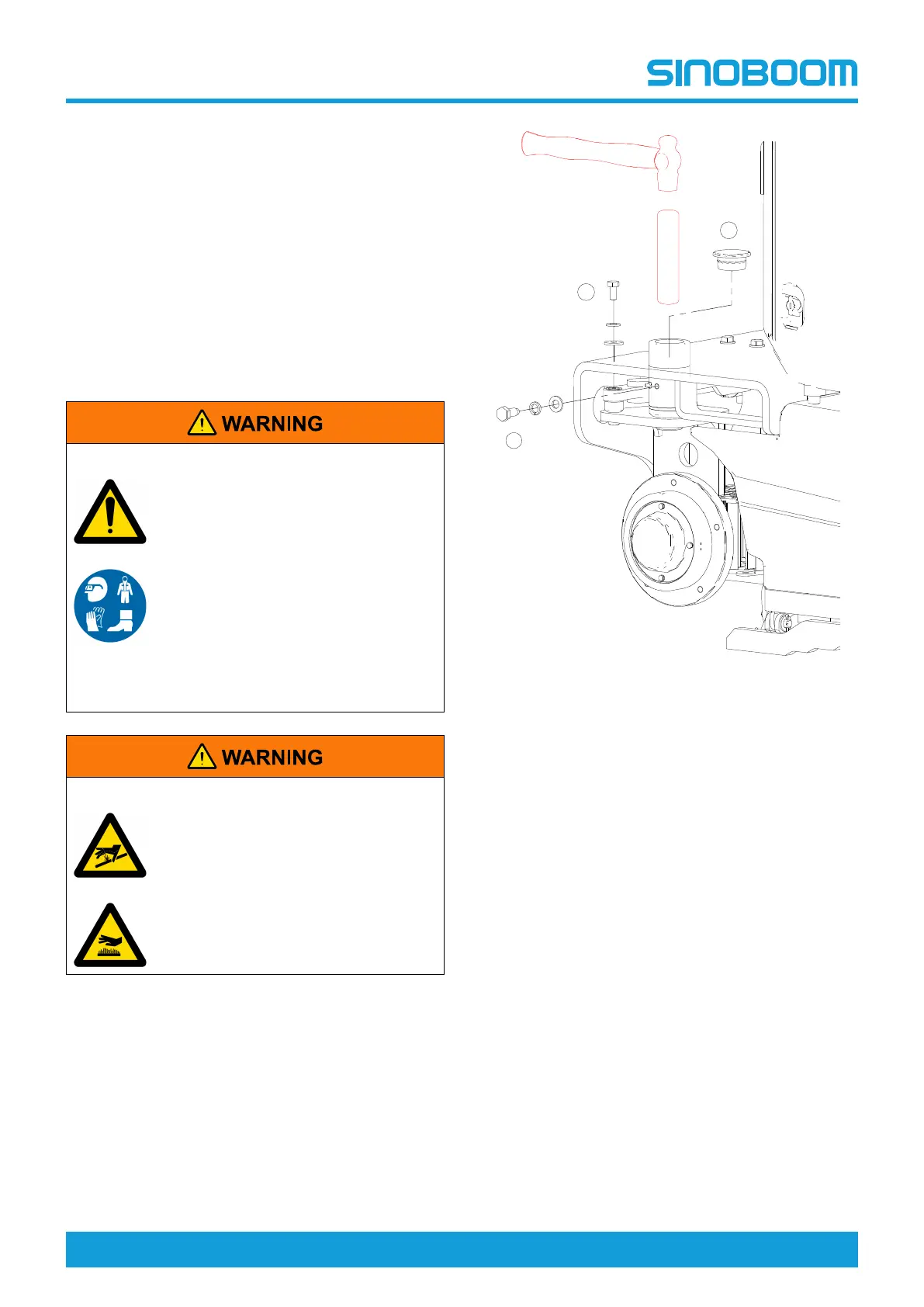
2. Removal
Figure 5-4
1. Disconnect the main power supply.
2. Disconnect all power inputs to the machine (such
as the battery charger).
3. Place a jack of sufficient capacity under the chassis
on the side for removal, raise the jack to make the
wheels off the ground.
4. Using a suitable lifting device, remove the wheels.
For details, see Tires and Rims, page 5-9.
5. Attach the lifting straps of a suitable crane to the
wheel support, be sure that the wheel support will
not fall with fasteners removed.
6. Remove the fastening bolts and shims at the
position #1 as indicated.
7. Remove the fastening bolts and shims at the
position #2 as indicated.
8. Remove the plug at the position #3 as indicated.
9. Using brass drift and mallet, tap the wheel support
out.
 Loading...