© Mar. 2022 5-28 GTTZ10EJ Maintenance Manual
MAINTENANCE
4. When the max drive speed is achieved with the
machine front wheels just reaching the reference
line, quickly release the joystick.
5. Measure the braking distance of the machine.
Result:Braking distance≤0.35m (1ft 2in).
6. If the braking distance exceeds the value range,
immediately tag and remove the machine from
service.
Operating position
1. Draw a line on the ground as a reference.
2. Start the machine.
3. Push the drive function button, then press and hold
the enable button on the joystick and slowly deflect
forward the joystick to full stroke.
4. When the max drive speed is achieved with the
machine front wheels just reaching the reference
line, quickly release the joystick.
5. Measure the braking distance of the machine.
Result:Braking distance≤0.05m (2in).
6. If the braking distance exceeds the value range,
immediately tag and remove the machine from
service.
Brake Release Function
1. Preparation
UNSAFE OPERATION HAZARD
• Corden off the area before testing.
• Before testing, Position the
machine on a level, firm surface
clear of obstructions.
• The test should be performed
from the ground using the ground
controls.
• Unless in case of emergency
situations, malfunctions, power
loss or during loading/unloading,
do not tow/drag the machine.
• Before releasing the drive brake,
be sure the machine is on a level
surface or safely choked.
2. Testing the brake release function
Method 1:
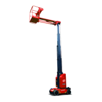
1. Choke wheels securely to prevent motion of the
machine.
2. Be sure the path is clear of obstructions, and the
power disconnect switch in off position.
3. Move upward the the brake release switch.
Figure 5-34
4. When a beef sounds, it indicates the brake is
released and the machine is all set for the towing/
dragging.
5. After the towing/dragging is complete, position the
machine on a firm level surface.
6. Choke wheels securely to prevent motion of the
machine.
7. Move again the brake release switch, or push in the
emergency stop button, or turn the key switch to off
position, to engage the brake.
8. Remove the chokes as desired.
Method 2:
1. Choke wheels securely to prevent motion of the
machine.
2. Be sure the path is clear of obstructions, and the
power disconnect switch in off position.
3. Remove the both end cap bolts and brake cover
from the wheel reducer.
 Loading...