After the first LED was turned on, the second LED that indicates the “ PLL LOCK” will must
be turned on, and the following message will be shown:
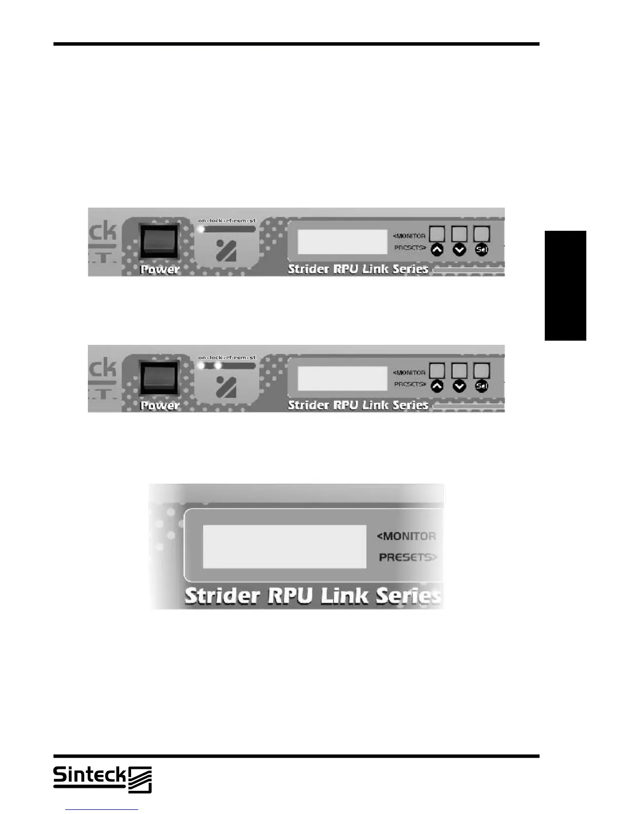
The unit is equipped with a LCD display with 2 lines on which several menus are shown. A
general view of the menus of the unit are shown in the illustration.
On the center of the display, depending on the case, the following symbol will be shown:
~
The parameter indicated can be modified in the menu CHANNEL, CONTRAST, AUDIO
LEVELADJUST,AUDIO MUTEAND CONFIG HOLD.
When the unit is switched on, the LCD display shows the predefined view, with the graphical
representation of the channel set and stops there, like the following sequence:
PLL LOCKED
In this view, the frequency of operation is shown:
FREQ. 452,50 MHZ
CHANNEL~ 10
Note that this moment if possible to change the frequency of operation on the Strider
Transmitter Link.
REMARK: Make sure that the antenna can respond to all frequencies of the Strider Link,
that has 5MHz bandwidht at minimum. The Strider Receiver Link has a dual cavity system
with high gain, if the antenna is out of the central frequency the user will note that the level of
RF-in is less than “MAX” if the Strider Transmitter link is operating near from this receiver.
03/P/39
 Loading...