42
PARTS LIST - 01704
Ref. No. Description SIP Part No. Ref. No. Description SIP Part No.
1. Base WD01-00793 35. Washer M8 WD01-00672
2. Column flange WD01-00794 36. Motor plate WD01-00820
3. Spring washer M10 WD01-00795 37. Nut M12 WD01-00821
4. Bolt (M10 x 25) WD01-00796 38. Grub screw (M8 x 10) WD01-00689
5. Rack WD02-00280 39. Motor pulley WD01-00822
6. Column WD02-00281 40. Motor WD01-00823
7. Screw (M6 x 12) WD01-00740 41. Spring washer M12 WD01-00676
8. Rack collar WD01-00799 42. Nut M8 WD01-00687
9. Screw (M6 x 16) WD01-00708 43. Cam pin WD01-00824
10. Handle cap WD01-00800 44. Cam WD01-00825
11. Screw (M8 x 20) WD01-00801 45. Washer WD01-00826
12. Spring washer M8 WD01-00673 46. Speed label WD01-00827
13. Handle knob WD01-00802 47. Nut M5 WD01-00697
14. Handle WD01-00803 48. Pulley cover WD01-00828
15. Knob WD01-00804 49. Washer M6 WD01-00702
16. Scale WD01-00805 50. Microswitch WD01-00706
17. Connection WD01-00806 51. Washer M6 WD01-00702
18. Label WD01-00807 52. Spring washer M6 WD01-00707
19. Roll pin (5 x 18) WD01-00808 53. Screw (M6 x 16) WD01-00708
20. Pinion shaft WD01-00809 54. Microswitch holder WD01-00709
21. Warning label WD01-00685 55. Nut M6 WD01-00710
22. Roll pin (6 x 18) WD01-00760 56. Eccentric shaft WD01-00829
23. Indicator WD01-00811 57. Centre pulley WD01-00830
24. Belt tension handle WD01-00812 58. Bearing 6202 WD01-00771
25. Circlip WD01-00813 59. Circlip WD01-00831
26. Locking handle WD01-00814 60. Belt O-500 WD01-00832
27. Roll pin (6 x 18) WD01-00760 61. Belt O-565 WD01-00833
29. Screw (M5 x 10) WD01-00726 62. Spindle pulley WD01-00834
30. Circlip WD01-00816 63. Circlip WD01-00713
31. Shaft WD01-00817 64. Spindle shaft WD01-00835
32. Adjusting shaft WD01-00818 65. Bearing 6203 WD01-00714
33. Washer M12 WD01-00819 66. Knurled screw WD01-00836
34. Bolt (M8 x 25) WD01-00695 67. Circlip WD01-00704
19
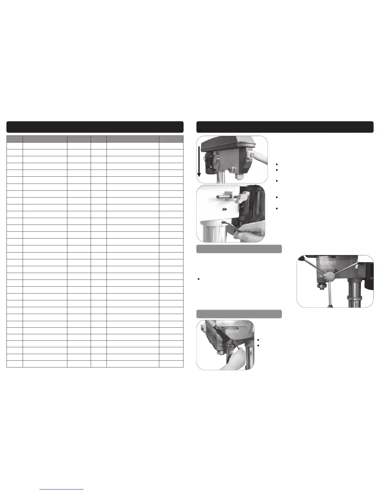
ASSEMBLY INSTRUCTIONS….cont
Carefully raise the head above the column.
Ensure that the hole in the bottom of the drill
head lines up with the column.
Lower the drill head down the column taking
care that the head and the column stay
square with each other.
Line up the spindle with the table and base
(011).
Secure in place by tightening the 2 x grub
screws on each side (012).
FIT THE FEED HANDLE - 01700 & 01701
To fit the feed handles; simply screw them
into the hub, as shown (013).
FIT THE FEED HANDLE - 01702 - 01708
Fit the cast feed handle over the hub.
Secure in place by tightening the 3 x screws, as
shown (014).
011
012
013
014
 Loading...