ASSEMBLY AND OPERATION
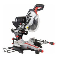
SETTING THE MITRE ANGLE
The saw is capable of mitre angles of up
to 45° to the left, and 60° to the right
(fig. 15).
To obtain the desired angle; release the
lock handle, turn to the correct angle
and lock the handle to secure.
Note: Raise the handle fully whilst setting
the desired mitre angle.
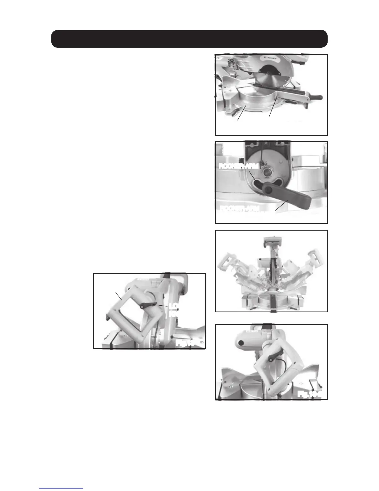
SETTING THE BEVEL ANGLE
The saw can be set to perform bevel
To obtain the desired angle; Loosen the
bevel lock handle (fig. 16).
Turn to the correct angle and lock the
handle to secure.
Note: The bevel lock button needs to be
pressed when setting the bevel angle to
the right, it will automatically lock when
the saw head is returned to 0°.
Fig.15
CLAMP ASSEMBLY
SCALE
ANGLE
POINTER
LOCKING
HANDLE
Fig.16
ROCKER-ARM
ROCKER-ARM
LOCKING SPANNER
Fig.17
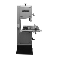
Fig.18-1
Fig.18-2
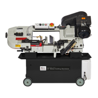
LOCKING
KNOB
FRONT
HANDLE
16
In order to make the cut more comfortable,
the main handle can be adjusted by 45°
left or right (fig. 18-1&18-2).
The clamp assembly can be mounted on
either side of the saw blade, and is designed
to safely hold the work-piece during cuts.
The clamp should be mounted on the
opposite side to the mitre cut, if the angle is above 15° (fig. 19).
Note: ensure that the all retaining screws etc are tight and that the work-piece is
fully secure before commencing cuts. This will reduce the risk of the work-piece
moving and causing personal injury and/or damage to the saw.