*Note: Make sure all the moving part locked before transportation.
• Adjusting the cutting angle (mitre).
All of the angles are accurately set at the factory, but over time some adjustments
may be required.
Slide the saw-head forwards (towards the fence) and lock the slide rail.
Loosen the mitre lock and set the saw at the 0° angle slot.
Set a right angled square against the blade and the fence, if the angle is not 90°,
loosen the 4 x cap head bolts that secure the fence in place. Adjust the fence
until a 90° is achieved and tighten the bolts to secure.
Check the angle pointer is reading 0°, if not, loosen the securing screw, set to 0°
and re-tighten the screw.
• Adjusting the cutting angle (bevel).
Slide the saw-head forwards (towards the fence) and lock the slide rail.
Loosen the bevel angle lock and set the saw-head at 0° and lower the saw-head
and lock in place.
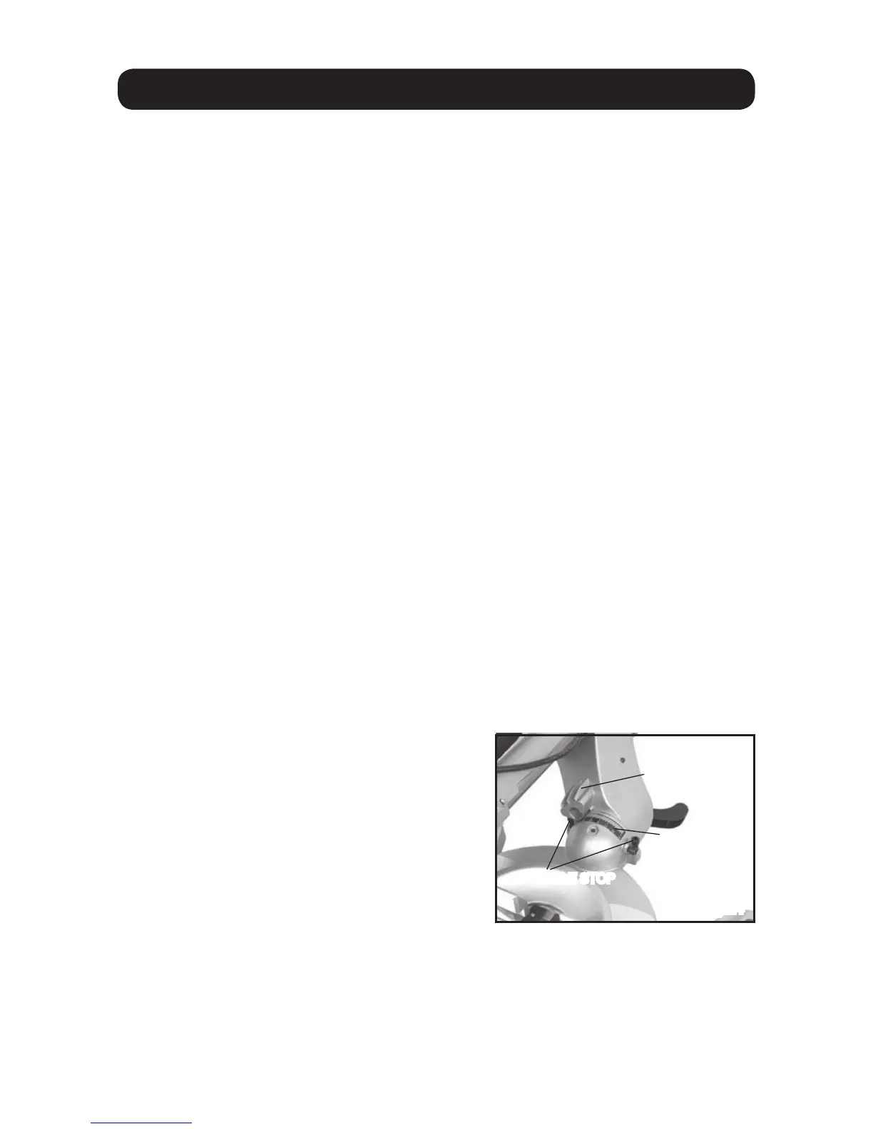
Set a right angled square against the blade and the main saw table, if the angle is
not 90°, loosen the lock nut on the 0° stop bolt (fig. 24) and turn the cap head bolt
until true 90° between the blade and the saw bed is achieved. Tighten the lock nut
to secure.
To adjust the 45° angle; Turn the saw head fully to the left and check the angle
between the blade and the saw table with a 45° set square. If the angle is not 45°
loosen the lock nut on the 45° stop (fig. 24) and turn the cap head bolt until true 45°
is achieved, Tighten the lock nut to secure.
Turn the saw head fully to the right and follow the instructions above to set the angle
on the right hand bevel angle. Return the saw head to the middle (0° ), check the
angle pointer is reading 0°, if not, loosen the securing screw, set to 0° and re-tighten
the screw.
MAINTENANCE
Fig.24
SCALE
ANGLE STOP