Operation and Installation CD401MR-SC
Date: 2022-09-26Page 8 of 48
CHAPTER 1. Physical installation
____________________________________________________________________
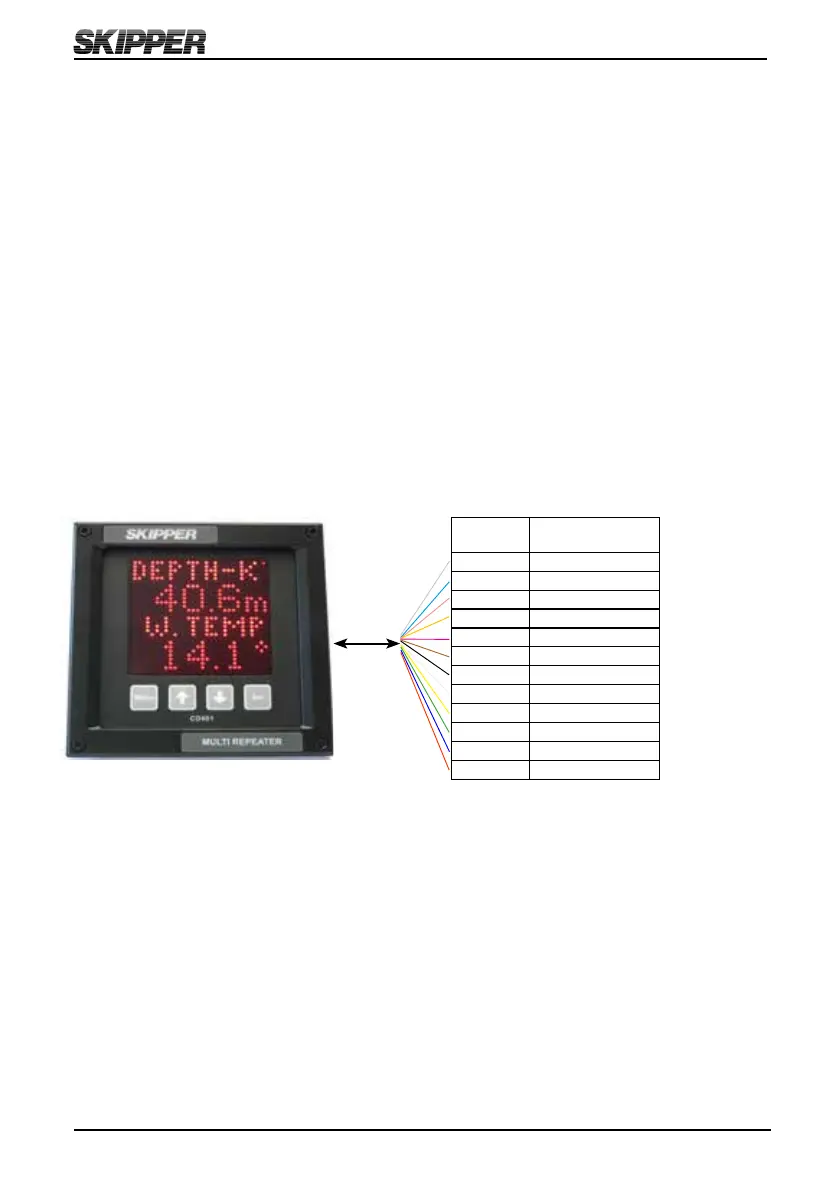
The Multi Repeater CD401MR is a stand alone unit and does not require additional
circuitry. It should be supplied by a 24 V (19 V-36 V) 25 W DC supply and the cabling
of the system is as per diagram below. The unit is supplied with 2 m of cable (12 core).
This can be extended without problem. Only the wires in use need extending.
Note: Mounting drawing is available in Appendix 1.
Color
Codes
Signals
Grey NMEA OUT A
Turquoise NMEA OUT B
Pink NMEA2 IN A
Orange NMEA2 IN B
Violet DIM DWN B
Brown DIM DWN A
Black DIM UP B
White DIM UP A
Yellow NMEA IN A
Green NMEA IN B
Blue 0 V
Red +24 V
2 m
NOTE
Compared to the CD401MR-SA/SB variants NMEA, A and B are switched , and
NMEA out is replaced by NMEA 1 in this version (See appendix 3.)