11
6 TDMA
Time Division Multiple Access(TDMA) is achannel access methodfor shared medium networks. It allows several units to share
the samefrequency channelby dividing the signal into different time slots. The units transmit and receive on the same frequency
in a synchronized manner. Every unit transmits in its own dedicated time slots. On the other time slots said unit receives the trans-
mission sent by the other units that are members of the same network (which are also transmitting on their own dedicated slots).
TDMA requires a synchronization system. The system is synchronized internally, externally or via GPS (synchronization varies
between topologies and method used).
The SkyHopper PRO unit uses TDMA regardless of the application type, PTP or PTMP.
7 PTP (Point-to-Point)
A PTP network is a radio link between 2 SkyHopper PRO units. The conguration (frequency and prole) of both units must be
the same with only one difference - one unit is congured as a Remote Unit while the other unit is congured as a Controller Unit.
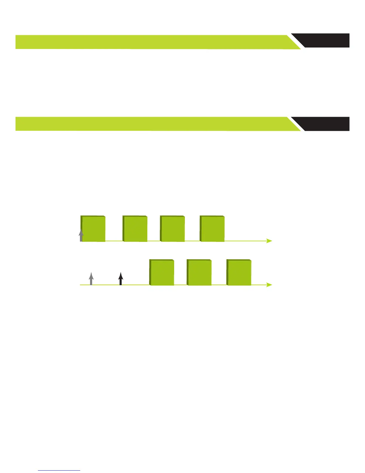
The Remote Unit works with its internal clock and synchronizes the Controller Unit. After power-up, the Remote Unit starts trans-
mitting regardless of link status. The Controller Unit however, does not transmit and stays in Rx mode, trying to acquire synchroni-
zation by nding a preamble (synchronization pattern). As soon as the Controller Unit recognizes the pattern, it starts to transmit
according to its allocated time slot.
The transmission bandwidth ratio is predened as part of the prole conguration. It can be symmetric when full duplex commu-
nications are required (50% to each unit) or asymmetric up to 10% to one unit (remote or controller) and 90% to the other unit.
Figure 5: Transmit frames of the remote unit and controller unit from Power Up
► Note: A viewer unit acts like a Controller unit but with one major change, it does not transmit
and only receives.
7. 1. PTP Link Step-by-Step Conguration
In order to build a PTP link, two SkyHopper PRO units are required. One unit acts as a remote unit, while the other as a
controller unit.
1. Connect antennas to RF1 and RF2 connectors, and power up the unit.
! CAUTION – Powering up a unit without connecting the antennas can cause irreparable damage to the unit.
2. Connect the unit to a PC using a standard Ethernet Cat 5 cable.