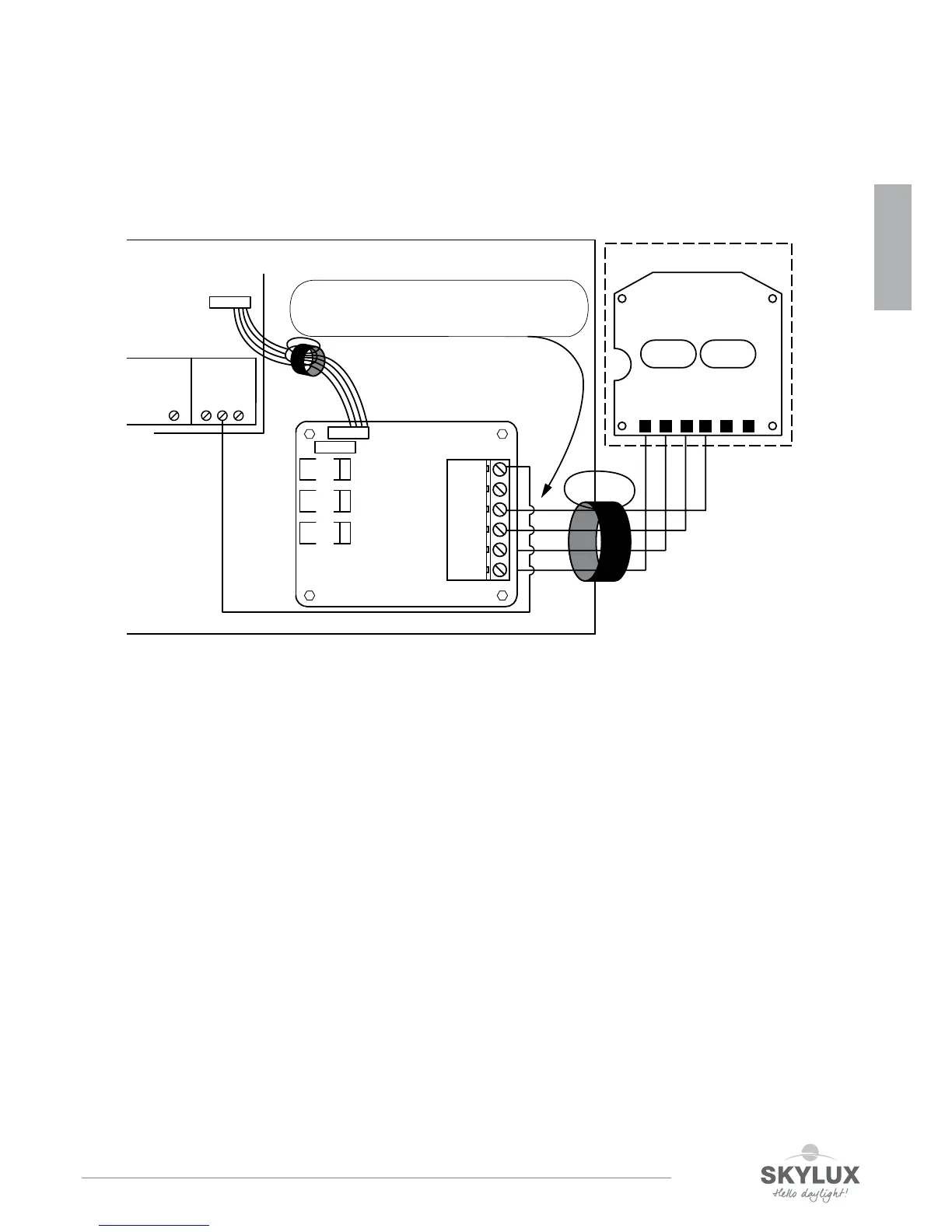
External priority switch for remen
The optional add-on PCP (SVM AddOn) is already connected. With correct SW (Version 042 or higher), LD3 + LD2 ash
for 5 sec. when communication has started. Connect the priority switch as shown on the electrical scheme. Line monitor-
ing is done on the close (1-3) and open (1-4) outputs of the “add-on” PCB and is indicated by LD3 and LD2. Therefore
in the priority switch 10kΩ resistors are integrated. To avoid confusion there can be only one priority switch.
Information about the LED-indications: see page 21.
SVM addon
54321 6
CLOSE OPEN
GND
OPEN
CLOSE
LED
AL
MAIN PCB
If present, remove resistors
when connecting priority switch
LED
CLOSE
OPEN
GND
GND
GND
POWER
OPEN
CLOSE
PRIOR
external priority switch
CONTROL
LINK
PROGRAM
LD1
LD2
LD3
GRE
RED
RED
ComfortWeather
24V
Gnd
Weather
22 23
Gnd
20 21
PRIOR
ENGLISH
 Loading...