E_MH_Installation_instruction_Skycom_Skymax_CE 01/10/2016
10/26
Fire switches
The re switch will contain the following:
• Breakable glass window and red control button, activated by pressure - this puts
the control unit in ALARM status, by which the motor output is activated (for
normal service and testing the lid can be opened with a key).
• RESET button which brings the control unit out of the alarm status and starts
the closing sequence for about 180 seconds. Please note that RESET does
not cancel errors in the system, e.g. line errors etc. These must be found and
corrected. When a detector is still alive after reset, the control will go immediately
in alarm status again.
• RED LED indicates that the control unit is in ALARM status and that the motor
output either is or has been activated.
• YELLOW LED indicates faults on the system - please call for a service
technician.
• GREEN LED indicates that the system is in normal operation status without
errors.
The master control has an integrated priority re switch.
Additional connection of the external re switches are made as shown on the
drawing.
When the control is fully loaded, max. 8 external re switches can be connected.
When there is no load (Master), max. 10 re switches can be connected.
The installation with re switches must be terminated with a resistor (10kΩ -
27kΩ) in the last switch in order to establish the line monitoring correctly – this
can either be done by moving the factory mounted resistor from the terminal
strip to the last re switch or connect jumper J1 in the re switch (by this a
10KΩ resistor is also connected).
By means of DIP switches the control unit has different possibilities of settings
for the input to the re switch:
DIP 1 (Con.Fire.Sw):
On = ALARM status from 500-3KΩ, (indication of line error by direct short circuit
or open circuit).
Off = ALARM status from 0-3KΩ (indication of line error by open circuit).
DIP 2 (Fail Safe):
On = Any line error on re switch or smoke detector puts the control unit in
ALARM status. This function can be used if cables to re switches and smoke
detectors are not reproof.
Off = An error status does not report ALARM status.
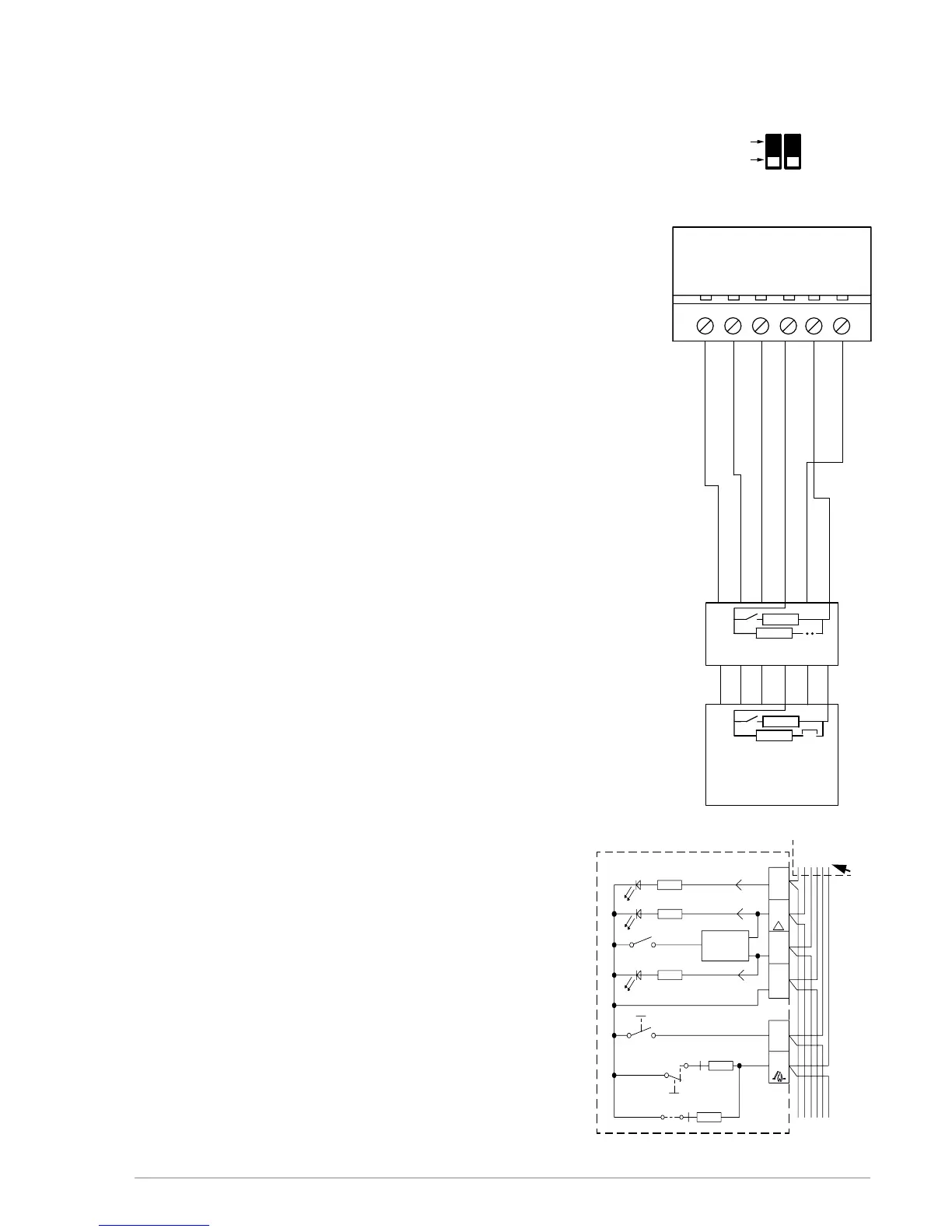
Terminals BVT
1. green LED OK (lights when OK and while closing)
2. yellow LED (lights on error)
3. red LED alarm (emergency opening)
4. ground (-)
5. not used
6. re switch reset
7. re switch emergency opening
Jumper J1 must only be set in
the last or only re switch
Fail. 24V
ALARM
OK 24V
6
4
3
2
1
4
3
2
1
J1
7
6
4
3
2
1
Gnd
11 12
24V
10 13
7
J1
7
6
FIRE
15
Reset
14
21
FAIL SAFE
Con. Fire. Sw
DIP
NO
OFF
ON
Red LED
Yellow LED
Green LED
2,2 kΩ
2,2 kΩ
10
K
Ω
Last manual control
point
Fit Jumper J1 for line
monitoring
Manual control point.
Break glass (BVT) No. 1
10
K
Ω
Break glass (BVT)
 Loading...