E_MH_Installation_instruction_Skycom_Skymax_CE 01/10/2016
14/26
More controls connected in one re group (bus connection)
When there is only 1 control unit in the re group, terminals
A 1 2 3 and B 1 2 3 are not used. The communication is
interrupted by removing all the jumpers.
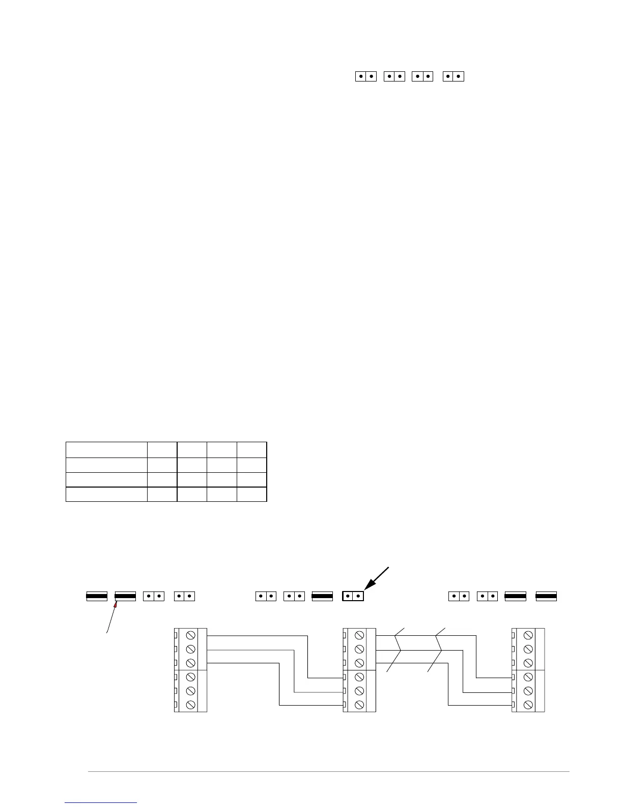
By means of a bus communication it is possible to make 2 – 35 control units to work as a complete system. The control
units communicate with each other via a 3 wire bus connection.
Terminal no. A1, A2, A3 are for the incoming connection and B1, B2, B3 for the outgoing connection.
In the rst control unit start Bus J4 has to be on. This control is Master and J5 must therefore also be on. Following con-
trol unit is a slave and therefore J6 must be connected. In the last slave unit, J7 and J6 must be connected to terminate
the bus cable.
ALARM: Alarms from Manuel Control Point smoke-/heat detectors are controlled locally. When DIP11 is set, the control
will go into alarm state if another control connected on the BUS enters alarm state.
RESET: If the reset button on one control or in one re switch is activated, the reset function on all connected controls is
activated and starts the closing function on all motor output for approx. 180 sec.
COMFORT: The comfort operation can work locally on each control. When DIP10 is set the control will react on any
comfort signal send on the bus from another control.
If a wind- and rain sensor is connected, it will work on all control on the bus matter dip settings.
Function description for control units connected with bus connection
If more control units are connected by means of a bus connection, the following are monitored/communicated between
the control units:
- A detected bus error makes the LED LD7 on the main board light/ash.
- A detected bus error brings all controls on the bus connection in error condition (line error).
- If one of the control units in the network goes into alarm status, all go into alarm status.
- If one of the control units goes into a certain error status (line error, AC error, battery error or bus error), the
other control units also go into error status – the type of the error is indicated on the board of the front plate of
all control units – on the control unit(s) which have not caused the error, the ok LED on the board of the front plate
ashes at the same time as the error. On the control unit(s) which have caused the error, the OK LED is switched
off.
Factory settings of Master, Slave & Skycom Skymax CE
J4 J5 J6 J7
Master ON ON OFF OFF
Slave OFF OFF ON ON
Skycom Skymax OFF OFF OFF OFF
 Loading...