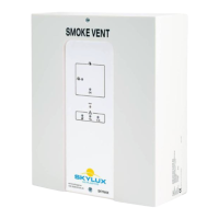
External signal output, Fire Alarm Panel and other control systems
The control panel can forward alarm situation to external connected systems by
means of potential free contacts on the terminals 4 (com), 5 (NC) and 6(NO).
The control panel can forward failure condition to external connected systems by
means of potential free contacts on the terminal 7 (com), 8(NO) and 9(NC).
Alarm and error contacts work parallel on all controls connected with bus connec-
tion.
DIP6 (fail relay):
On = Fail relay changes function to indicate open/closed smoke hatches.
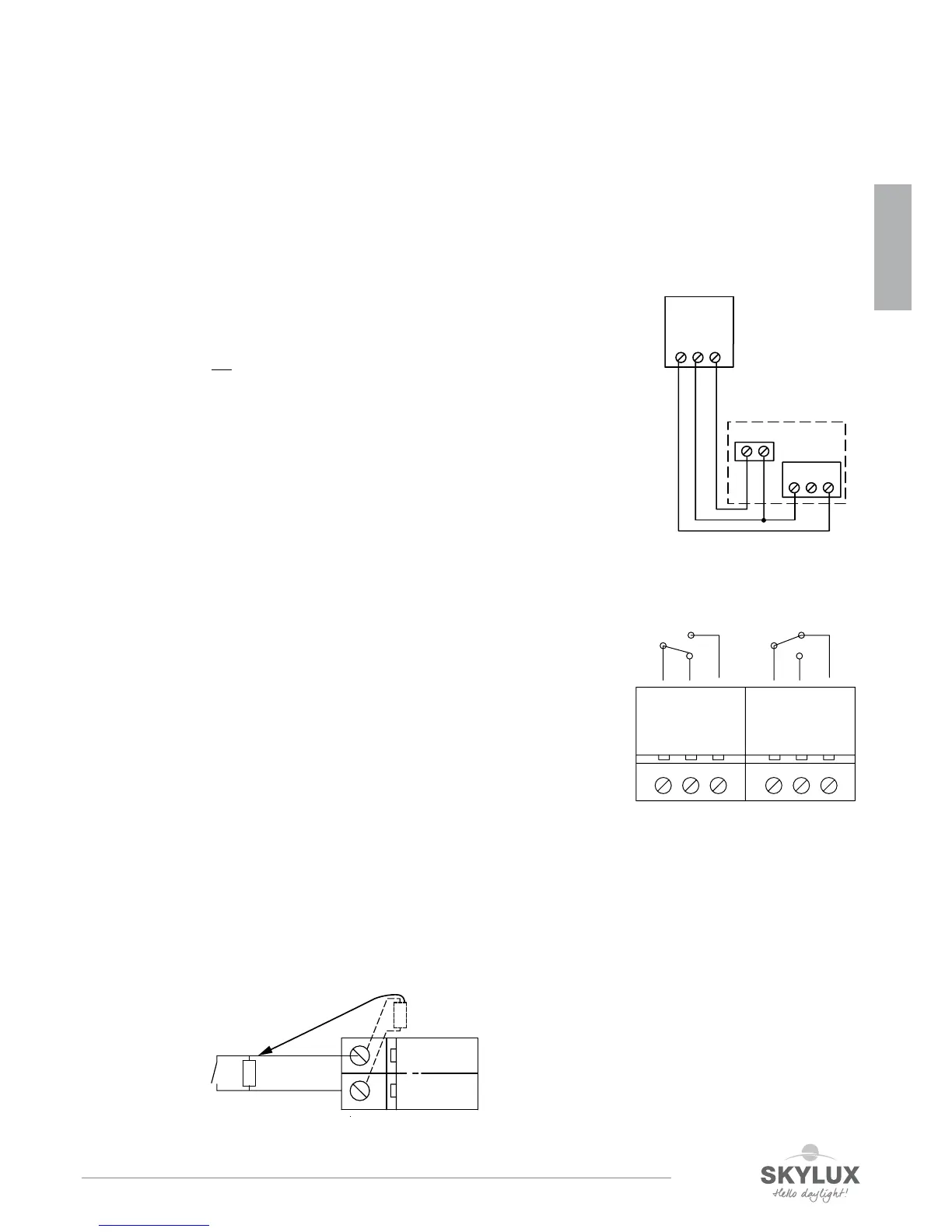
How to make a connection from a Fire Alarm Panel
The control panel can receive potential free alarm signals from e.g.
AFA systems on the input to re switch or smoke-/heat detector.
Terminal 16 and 17.
Line monitoring resistor must be tted over the contact of the AFA system.
GND
16 17
Smoke
10 kΩ
Normally open
10 kΩ
Supplied with Panel
Weather sensor / Close all function
Install the rain- and wind detection as close as possible to the smoke hatch, at a place, where
the wind speed is equal to the wind speed of the smoke hatch (do not install the detector at eg
the outside of the roof edge trim).
The smoke hatches should be closed when the wind is above 6 m/s.
LED LD3 on the main board indicates active weather sensor - lights as long as input is active.
As long as the weather sensor is active, the smoke hatches cannot be opened with comfort
switches.
The weather sensor closes on all controls which are connected through bus connection.
On the input to weather station a weekly timer can be connected which makes sure that
everything is closed, e.g. by end of a working day.
The 24V power supply (terminal 22 & 23) for the weather sensor is standard set this
way (J11) that it does not function on batteries.
If battery functioning is needed, then mount J11.
This is possible at PCB V5 and the following versions (as from March 2015).
Be aware of the reduced standby time due to current consumptions.
Factory setting weather sensor = test = Pos 0 = delay 10s + highest sensibility.
Recommended settings weather sensor: Pos 4 = 4m/s (delay = 10 min)
For more details, consult the installation instructions of the wind-and
rain detector AWR-24/250.
Weather
24V
Gnd
Weather
22 2321
NC
NO
COM
24V
AC/DC
WIND & RAIN
AWR-24/250
ENGLISH
 Loading...